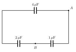
Q.For the arrangement of the capacitors as shown in figure, the net capacitance between points A and B is –
🔒You're viewing a preview — the full solution, concept, methods & PYQ mapping are locked.
🔒 Start your 14-day free trial to unlock the full solution →Concept understanding — Capacitors in Series and Parallel
In a SERIES combination, every capacitor carries the SAME charge Q, and the equivalent capacitance obeys CS1=C11+C21+⋯ -- always SMALLER than the smallest individual capacitor, and used to divide a high voltage safely across several capacitors (the smallest-capacitance capacitor in the chain always bears the largest share of the voltage). …
Redrawing the network reduces it to two capacitors in series whose combination sits in parallel with a third, so combining the series pair first and then adding the parallel branch gives the equivale …
Redrawing the loop as a triangle of three capacitors (4 μF, 2 μF, 1 μF) between three nodes, the two in series combine and that combination sits in parallel with the third.
Why / setup: Label the top-left/bottom-left corner (joined by the plain left wire) as node X, and the bottom-right corner as node Y. Since the right wire is plain, Y is the same node as A. So the circuit reduces to three capacitors between three nodes: A–X (4 μF, the top edge), X–B (2 μF, left half of the bottom edge), and B–A (1 μF, right half of the bottom edge, since B–Y is the 1 μF capacitor and Y=A).
Steps: …
Showing the 12 most recent of 14 on this concept.
- CBSE 2025Set D1 markMCQQ.In parallel combination of condensers which quantity remains same for each condenser? (A) Charge (B) Energy (C) Potential difference (D) Capacity
›Reveal solutionSolution
In a parallel combination, every capacitor shares the same two terminals, so the potential difference across each is identical.
When capacitors are connected in parallel, their plates are joined to the same pair of nodes. The voltage across each capacitor therefore equals the common terminal voltage V.
…
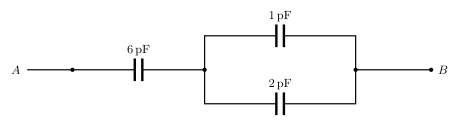
- CBSE 2025Set ANNUAL1 markQ.Determine the equivalent capacitance between the points A and B in the adjoining figure.
›Reveal solutionSolution
First combine the two parallel capacitors, then combine that result in series with the 6 pF capacitor.
Step 1 — parallel combination: the 1 pF and 2 pF capacitors are connected in parallel between the two junction nodes:
Cparallel=1+2=3 pF
Step 2 — series combination: this 3 pF combination is in series with the 6 pF capacitor between A and B:
…
- CBSE 2025Set ANNUAL1 markMCQQ.Three capacitors each having capacitance C are connected in series. Their equivalent capacitance is(a) 3C(b) 3/C(c) C/3(d) 1/3C
›Reveal solutionSolution
Capacitors in series combine like resistors in parallel: 1/C_eq = 1/C1 + 1/C2 + 1/C3, so three equal capacitors C give C_eq = C/3.
For capacitors in series, the same charge Q flows onto each, and the total voltage is the sum of individual voltages, which leads to:
1/C_eq = 1/C + 1/C + 1/C = 3/C
C_eq = C/3
…
- CBSE 2025Set ANNUAL1 markQ.In which order capacitors are connected to increase resultant capacitance?
›Reveal solutionSolution
Parallel combination increases equivalent capacitance; series combination decreases it.
For capacitors C1,C2,C3,… connected:
- In series: Ceq1=C11+C21+C31+… — the equivalent capacitance is always smaller than the smallest individual capacitance (because effectively the plate separation increases / the charge stored is the same on each but the total voltage adds up). …
- CBSE 2025Set ANNUAL1 markQ.What is the equivalent capacitance between A and B ?
›Reveal solutionSolution
This 5-capacitor network is a balanced capacitor bridge (all five are equal, 4 μF each), so the diagonal 'bridge' capacitor carries no charge and can be removed; what's left is two 2 μF series paths in parallel, giving 4 μF.
Label the apex of the triangle P and the mid-point node of the two base capacitors Q. The network is:
- A−P: 4 μF (left slant)
- P−B: 4 μF (right slant)
- A−Q: 4 μF (left half of base)
- Q−B: 4 μF (right half of base)
- P−Q: 4 μF (the bridging capacitor)
This is exactly a Wheatstone-bridge-like arrangement. A capacitor bridge is balanced (no charge on the bridge arm, hence no potential difference across it) when
CAQCAP=CQBCPB
…
- CBSE 2024Set ANNUAL1 markMCQQ.The ratio between resultant capacitances Cs and Cp of two equal capacitors in series combination and parallel combination respectively is(a) 1(b) 1/2(c) 1/4(d) 1/8
›Reveal solutionSolution
Two equal capacitors C in series give C_s = C/2; in parallel they give C_p = 2C; the ratio C_s/C_p = 1/4.
Let each capacitor have capacitance C.
Series combination: for two capacitors in series, 1/C_s = 1/C + 1/C = 2/C, so C_s = C/2.
Parallel combination: for two capacitors in parallel, capacitances simply add: C_p = C + C = 2C.
Now form the ratio:
C_s/C_p = (C/2)/(2C) = 1/4
…
- CBSE 2024Set ANNUAL1 markQ.Two capacitors of capacities 5μF and 10μF respectively are connected in series. Calculate the resultant capacity of the combination.
›Reveal solutionSolution
Reciprocal-sum rule for capacitors in series.
Ceq1=C11+C21=51+101=102+101=103
Ceq=310≈3.33 μF …
- CBSE 2023Set F1 markMCQQ.Three capacitors of capacitance 6 μF are available. The minimum and maximum capacitances obtained are (A) 3 μF, 12 μF (B) 2 μF, 12 μF (C) 2 μF, 18μF (D) 6 μF, 18 μF
›Reveal solutionSolution
All in series ⇒ 2 μF (minimum); all in parallel ⇒ 18 μF (maximum).
For three equal capacitors of C=6μF:
…
- CBSE 2023Set ANNUAL1 markMCQQ.For the arrangement of the capacitors as shown in figure, the net capacitance between points A and B is –(a) 1.7 μF(b) 2.33 μF(c) 2.8 μF(d) 7 μF
›Reveal solutionSolution
Redrawing the loop as a triangle of three capacitors (4 μF, 2 μF, 1 μF) between three nodes, the two in series combine and that combination sits in parallel with the third.
Why / setup: Label the top-left/bottom-left corner (joined by the plain left wire) as node X, and the bottom-right corner as node Y. Since the right wire is plain, Y is the same node as A. So the circuit reduces to three capacitors between three nodes: A–X (4 μF, the top edge), X–B (2 μF, left half of the bottom edge), and B–A (1 μF, right half of the bottom edge, since B–Y is the 1 μF capacitor and Y=A).
Steps: …
- CBSE 2022Set ANNUAL1 markMCQQ.The expression for the effective capacitance C of two capacitors of capacitance C1 and C2 combined in series is -(a) C=C1+C2(b) C1=C11+C21(c) C=C1×C2(d) C1=C11×C21
›Reveal solutionSolution
For capacitors in series, reciprocals of capacitance add.
…
- CBSE 2022Set I1 markMCQQ.If n capacitors of equal capacity C_1 are connected in parallel, the equivalent capacity will be (A) C = n/C_1 (B) C = C_1/n (C) C = nC_1 (D) C = n^2 C_1
›Reveal solutionSolution
Parallel: C=nC1.
When capacitors are connected in parallel, they share the same potential difference and their capacitances add:
C=C1+C2+⋯+Cn.
If all n capacitors have equal capacitance C1, then
C=nC1.
…
- CBSE 2021Set A1 markMCQQ.Equivalent capacity between A and B in figure is (A) C (B) C/2 (C) 2C (D) 2/C
›Reveal solutionSolution
Series C with a parallel pair (2C) gives 2C/3 — not one of the printed options, so the option set appears misprinted.
From the figure description: from A a capacitor C is in series, then two capacitors each of value C are in parallel leading to B.
Step 1 — the two parallel capacitors combine by addition:
C∥=C+C=2C.
Step 2 — this parallel block is in series with the first capacitor C:
Ceq1=C1+2C1=2C2+1=2C3⇒Ceq=32C.
The result 2C/3 does not match any of the options (a) C,
(B) C/2,
(C) 2C, …
🎓Unlock everything free for 14 days
- ✓Full step-by-step solutions
- ✓Concept-first explanations
- ✓Methods, shortcuts & mistakes
- ✓PYQ mapping + timed mock tests
Full access for 14 days. No credit card required.