Q.In an alternating current circuit consisting of elements in series, the current increases on increasing the frequency of supply. Which of the following elements are likely to constitute the circuit?
🔒You're viewing a preview — the full solution, concept, methods & PYQ mapping are locked.
🔒 Start your 14-day free trial to unlock the full solution →Concept understanding — Capacitive Reactance
Capacitive Reactance: The AC Resistance of a Capacitor
When you first meet a capacitor in a DC circuit, it behaves like a break in the wire once it's fully charged — no current flows. But in an AC circuit, something entirely different happens. The voltage keeps reversing, so the capacitor never finishes charging. It's constantly being filled, emptied, refilled, and re-emptied. This continuous back-and-forth means current does flow, but the capacitor resists that flow in a frequency-dependent way. That resistance is called capacitive reactance.
The Intuition: Why Frequency Matters
Imagine a water pipe with a flexible rubber membrane stretched across it (a crude capacitor). If you push water slowly from one side, the membrane bulges and eventually stops the flow — that's DC. But if you push and pull the water rapidly (AC), the membrane just vibrates, and water sloshes back and forth through the pipe. The faster you push-pull (higher frequency), the less the membrane impedes the flow. At very high frequencies, it's almost like the membrane isn't there.
In a capacitor, the "membrane" is the electric field between the plates. Higher frequency means the voltage changes faster, so the capacitor has less time to oppose the current. The result: capacitive reactance decreases as frequency increases.
The Precise Statement
Capacitive reactance XC is the opposition a capacitor offers to alternating current. It is measured in ohms (Ω), just like resistance. The formula is:
XC=2πfC1
Where:
- XC = capacitive reactance (ohms)
- f = frequency of the AC signal (hertz)
- C = capacitance (farads)
What the Formula Tells You
Three key relationships jump out:
- Inverse with frequency: Double the frequency, halve the reactance. At DC (f=0), XC becomes infinite — the capacitor blocks DC completely.
- Inverse with capacitance: A larger capacitor (more farads) offers less opposition. It can store more charge per volt, so it "gives way" more easily.
- No power dissipation: Unlike a resistor, a pure capacitor doesn't convert electrical energy to heat. Reactance is a reactive opposition — energy is stored and returned, not lost.
Do not confuse capacitive reactance with resistance. Resistance dissipates energy as heat; reactance stores and releases it. A capacitor in an AC circuit has zero real power loss (in the ideal case).
Phase: The Hidden Twist
There's a critical detail that separates reactance from resistance. In a purely resistive circuit, voltage and current peak at the same time — they are in phase. In a purely capacitive circuit, current leads voltage by 90∘ (or π/2 radians).
Why? Because current is the rate of change of charge: I=CdtdV. When the voltage is at its peak (not changing), the current is zero. When the voltage is crossing zero (changing fastest), the current is maximum. This quarter-cycle shift is baked into the definition of reactance. …
Why this formula?
Capacitive Reactance: Why XC=ωC1?
Let’s build the intuition from the ground up — starting with what a capacitor does in a circuit.
1. The Fundamental Behavior of a Capacitor
A capacitor stores charge. The defining equation is:
Q=CV
where:
- Q = charge on the plates (in coulombs)
- C = capacitance (in farads)
- V = voltage across the plates
But in an AC circuit, voltage changes continuously. So charge must also change — meaning current flows.
2. Relating Current to Voltage
Current is the rate of flow of charge:
I=dtdQ
Substitute Q=CV:
I=dtd(CV)
If C is constant (which it is for a fixed capacitor):
I=CdtdV
Key insight: The current through a capacitor is proportional to the rate of change of voltage, not the voltage itself.
3. Applying a Sinusoidal Voltage
In AC circuits, voltage is typically sinusoidal:
V(t)=V0sin(ωt)
where:
- V0 = peak voltage
- ω=2πf = angular frequency (rad/s)
Now find the current:
I(t)=Cdtd[V0sin(ωt)]=CV0⋅ωcos(ωt)
So:
I(t)=ωCV0cos(ωt)
4. The Phase Shift — Why It Matters
Notice:
- Voltage: sin(ωt)
- Current: cos(ωt)=sin(ωt+90∘)
Current leads voltage by 90∘ in a pure capacitor. This is the opposite of an inductor (where current lags).
5. Extracting the Reactance
Compare the amplitudes:
- Voltage amplitude: V0
- Current amplitude: I0=ωCV0
By Ohm’s law for AC (magnitude only):
Reactance=Current amplitudeVoltage amplitude=ωCV0V0=ωC1
Thus:
XC=ωC1=2πfC1
6. Why "Reactance" and Not "Resistance"?
- Resistance (R) dissipates energy as heat. …
In a series AC circuit the current is I=V/Z, so current rises as the impedance Z falls with increasing frequency.
- Resistance R is independent of frequency.
- Inductive reactance XL=2πfL increases with frequency.
- Capacitive reactance XC=2πfC1 decreases with frequency. …
Current increases with frequency only when the net reactance falls as f rises, and the sole element whose reactance decreases with frequency is the capacitor (XC=1/2πfC). So the circuit contains a capacitor (with a resistor) — an RC combination.
The current in a series AC circuit is set by the total impedance, I=V/Z. For a fixed supply voltage, the current grows whenever Z shrinks. So the question reduces to: which element makes the impedance fall as the frequency is raised?
1. How each element depends on frequency
- Resistor: ZR=R, constant — unaffected by frequency.
- Inductor: XL=2πfL — increases in proportion to frequency.
- Capacitor: XC=2πfC1 — decreases as frequency increases.
2. Test each simple circuit
- Pure resistor: I=V/R is independent of f — no change. Ruled out.
- Pure / series inductor: Z=R2+(2πfL)2 grows with f, so current falls. This is the opposite of what is observed. Ruled out.
- Pure / series capacitor: Z=R2+(2πfC1)2; as f rises the capacitive term shrinks, Z falls, and the current rises. This matches the observation. …
Method: Determining Circuit Composition from a Monotonic Current-vs-Frequency Trend
Use this for MCQs describing a current that consistently rises (or consistently falls) as frequency increases, and asking which elements must be present.
Steps
Step 1: Express current through impedance, and impedance through each element's own reactance law
I=V/Z, so current rises exactly when Z falls. For a series combination, list how each possible element's contribution to Z behaves with frequency f:
- Resistor: ZR=R — flat, no frequency dependence.
- Inductor: XL=2πfL — increases with frequency.
- Capacitor: XC=2πfC1 — decreases with frequency.
Step 2: Match the required monotonic trend to the one element whose reactance moves that way
If the current is stated to rise as frequency rises, you need Z to fall as frequency rises — the only element whose own reactance formula decreases with f is the capacitor. (Conversely, a current that falls with rising frequency points to an inductor, whose reactance grows with f.)
Step 3: Confirm by testing the simple series combinations
- Resistor only: I constant — rejected (no trend at all). …
- AP EAPCET 2026Set eng-2026-05-15-FN1 markMCQQ.In an ac circuit containing Resistance R and capacitance C, the current is I. Keeping the ac voltage constant, if the frequency is made 31, the current is 2I, then the ratio of initial reactance to the resistance is (A) (53)1/2 (B) (52)1/2 (C) (51)1/2 (D) (54)1/2
›Reveal solutionSolution
Capacitive reactance triples when frequency drops to a third; matching this against the given halving of current pins down XC/R=3/5 at the original frequency. Answer: (A).
Concept and Intuition
In a series R-C circuit, XC=2πfC1 is inversely proportional to frequency, while R stays fixed. The impedance Z=R2+XC2 sets the current I=V/Z at constant voltage. Lowering the frequency raises XC (capacitor becomes more 'blocking'), raising Z and lowering I — exactly the behaviour described.
Step-by-Step Solution
- Let the original frequency be f, with reactance XC and impedance Z1=R2+XC2, current I=V/Z1.
- At frequency f/3: XC′=2π(f/3)C1=3XC. New impedance Z2=R2+9XC2.
- Given new current is I/2, and V unchanged: Z2=2Z1, so Z22=4Z12.
- R2+9XC2=4(R2+XC2)=4R2+4XC2. …
- AP EAPCET 2026Set ap-2026-05-19-AN1 markMCQQ.Which of the following statements is / are true with respect to the circuit given below? I. Reading of A and V2 are always in phase II. Reading of V1 leads reading of V2 in phase III. Reading of A leads reading of V1 in phase [FIGURE] (an AC circuit: source V (an AC supply symbol) on the left of a rectangular loop; the top branch contains a capacitor C with a meter V1 connected across the top-left segment from the source to the node above C; from the node after C, a resistor R runs down to the bottom wire, and a meter V2 is connected in the rightmost branch parallel to R; a meter A is placed in the bottom wire of the loop, in series with the source) (A) I only (B) I and II (C) I and III (D) II and III
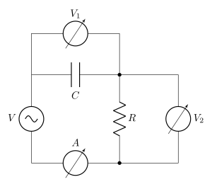
›Reveal solutionSolution
This is a series RC circuit: the ammeter A reads the common current, V2 reads the resistor voltage (in phase with the current) and V1 reads the capacitor voltage (lagging the current by 90∘). Statements I and III are true, so the answer is (C).
Concept
In a single series loop the current is the same everywhere, so the ammeter A measures the current common to C and R. The voltmeter V1 is across the capacitor and V2 is across the resistor. The two fixed facts you need:
- Across a resistor, voltage and current are in phase.
- Across a capacitor, the current leads the voltage by 90∘ (ELI the ICE-man: in a Capacitor, I leads E).
Statement I - A and V2 are in phase
V2 is the resistor voltage, which is always in phase with the current read by A. True.
Statement II - V1 leads V2 …
- AP EAPCET 2025Set ap-2025-05-19-AN1 markMCQQ.If a capacitor of 500 nF is connected to an ac source of frequency 1 kHz, then the capacitive reactance of the capacitor is (A) π103 Ω (B) π104 Ω (C) π2×10³ Ω (D) 2π×103 Ω
›Reveal solutionSolution
Direct substitution into XC=1/(2πfC) gives XC=103/π Ω.
Concept and Intuition
A capacitor's opposition to alternating current, the capacitive reactance, is XC=ωC1=2πfC1. It decreases with increasing frequency because a capacitor charges and discharges more easily (offers less opposition) when the applied voltage reverses direction faster.
Step-by-Step Solution
- Given: C=500 nF=500×10−9 F=5×10⁻⁷ F, f=1 kHz=103 Hz.
- XC=2πfC1=2π×103×5×10−71
- Compute the denominator: 2π×103×5×10−7=2π×5×10−4=10π×10−4=π×10−3. …
- AP EAPCET 2025Set ap-2025-05-20-FN1 markMCQQ.A bulb is connected in series with a capacitor to an ac supply. If the capacitance of the capacitor increases, then power of light emitted by the bulb (A) decreases (B) increases (C) does not change (D) becomes zero
›Reveal solutionSolution
This tests how a series R–C AC circuit's impedance changes with capacitance; increasing C lowers the capacitive reactance, raising the current and hence the bulb's power. Answer: power increases.
Concept and Intuition
A capacitor in an AC circuit offers an opposition to current flow called capacitive reactance, XC=ωC1. Unlike a resistor, this reactance depends inversely on capacitance: a bigger capacitor 'blocks' AC less. Since the bulb (a resistor) is in series with the capacitor, the same current flows through both. The total impedance of the series combination is
Z=R2+XC2.
Step-by-Step Solution
- Capacitive reactance: XC=ωC1. As C increases, XC decreases.
- Impedance of the series R–C circuit: Z=R2+XC2. Since XC decreases, Z decreases.
- Current in the circuit: I=ZVrms. Since Z decreases while Vrms (supply) is fixed, I increases. …
- AP EAPCET 2023Set ap-2023-05-23-FN1 markMCQQ.A capacitor and a resistor are connected in series to an ac source of variable frequency. When the frequency of the ac source become 31rd of its initial value, the current in the circuit decreases by 50%. The power factor of the circuit at the initial frequency is (A) 81 (B) 83 (C) 85 (D) 87
›Reveal solutionSolution
Using the current-halving condition to relate the reactance at two frequencies gives X02=53R2, and the power factor R/Z0 works out to 5/8.
Concept and Intuition
In a series RC AC circuit, impedance is Z=R2+XC2 where XC=ωC1 is the capacitive reactance. Lowering the frequency raises XC (harder for the capacitor to "pass" current), which raises Z and lowers the current for the same applied voltage — matching the given fact that current drops when frequency drops. The power factor cosϕ=R/Z measures how resistive (vs. reactive) the circuit's response is at a given frequency; it needs both R and XC at that specific frequency.
Step-by-Step Solution
- Let the initial angular frequency be ω0, reactance X0=1/(ω0C), impedance Z0=R2+X02, current I0=V/Z0.
- At ω0/3: reactance becomes X′=1/((ω0/3)C)=3X0 (reactance is inversely proportional to frequency).
- Current halves: I′=I0/2=V/Z′⇒Z′=2Z0.
- Square both impedances: Z02=R2+X02 and Z′2=R2+(3X0)2=R2+9X02.
- Substitute Z′2=4Z02: R2+9X02=4(R2+X02)=4R2+4X02.
- Rearranging: 5X02=3R2⇒X02=53R2. …
- AP EAPCET 2022Set eng-2022-07-04-AN1 markMCQQ.Capacitive reactance of a capacitor in an AC circuit is 3kΩ. If this capacitor is connected to a new AC source of double frequency, the capacitive reactance will become (A) 1.5kΩ (B) 3kΩ (C) 6kΩ (D) 5.2kΩ
›Reveal solutionSolution
XC∝1/f, so doubling the source frequency halves the capacitive reactance from 3 kΩ to 1.5 kΩ.
Concept and Intuition
A capacitor's opposition to AC current, XC=2πfC1, decreases as frequency increases — at higher frequency the capacitor charges and discharges faster, letting more current through for the same voltage.
Step-by-Step Solution
- XC,1=2πfC1=3kΩ at frequency f.
- At frequency 2f: XC,2=2π(2f)C1=2XC,1.
- XC,2=23=1.5kΩ. …
- AP EAPCET 2022Set eng-2022-07-06-AN1 markMCQQ.π50 μF capacitor is connected to a 250 V, 50 Hz AC supply. Then the rms current of the circuit is (A) 1.25 A (B) 4.9 A (C) 5 A (D) 6 A
›Reveal solutionSolution
Compute the capacitive reactance from f and C, then apply Ohm's law for AC: Irms=Vrms/XC=1.25 A.
Concept and Intuition
A capacitor's opposition to AC is the reactance XC=1/(ωC), which plays the role of "resistance" in V=IXC for rms quantities in a purely capacitive AC circuit.
Step-by-Step Solution
- ω=2πf=2π(50)=100π rad/s.
- XC=ωC1=100π×(π50×10−6)1.
- The π's cancel: 100π×π50×10−6=100×50×10−6=5000×10−6=5×10⁻³.
- XC=5×10−31=200 Ω. …
- AP EAPCET 2022Set eng-2022-07-07-FN1 markMCQQ.A 100 μF capacitor is connected to a 100 V, 50 Hz AC supply. The rms value of the current is (A) 3.14 A (B) 4.75 A (C) 2.33 A (D) 5.5 A
›Reveal solutionSolution
Standard AC-capacitor problem: compute the reactance, then use Ohm's law for AC to get the rms current, 3.14 A.
Concept and Intuition
In an AC circuit, a capacitor opposes current with a frequency-dependent reactance XC=ωC1=2πfC1 (unlike a resistor, this depends on frequency). Once XC is known, rms current follows exactly as in a resistive circuit: Irms=Vrms/XC.
Step-by-Step Solution
- C=100 μF=10−4 F, f=50 Hz, Vrms=100 V.
- XC=2πfC1=2π(50)(10−4)1=0.03141591≈31.83 Ω. …
- AP EAPCET 2022Set eng-2022-07-08-FN1 markMCQQ.Capacitive reactance of a capacitor in an AC circuit is 6 kΩ. If the same capacitor is connected to an AC source of double the frequency, the capacitive reactance will become (A) 6 kΩ (B) 3 kΩ (C) 1.5 kΩ (D) 8.5 kΩ
›Reveal solutionSolution
Capacitive reactance is inversely proportional to frequency, so doubling frequency halves it: 6kΩ→3kΩ.
Concept and Intuition
Capacitive reactance XC=2πfC1 decreases as frequency increases — a capacitor "conducts" AC more easily at higher frequencies. Since C is fixed here, XC∝1/f directly.
Step-by-Step Solution
- Original reactance: XC=2πfC1=6kΩ.
- New frequency: f′=2f. New reactance: XC′=2π(2f)C1=2XC. …
- AP EAPCET 2021Set eng-2021-08-23-AN1 markMCQQ.In an AC circuit containing only capacitance, the current ___________ (A) leads the voltage by 180∘ (B) remains in phase with the voltage (C) leads the voltage by 90∘ (D) lags the voltage by 90∘
›Reveal solutionSolution
For a capacitor in an AC circuit, the current is maximum when the voltage is changing fastest (zero crossing), which places current 90∘ ahead of voltage in phase.
Concept and Intuition
The current through a capacitor is I=CdtdV. If V=V0sinωt, then I=CV0ωcosωt=I0sin(ωt+90∘) — the current waveform is a cosine relative to the voltage sine, i.e., it peaks a quarter cycle before the voltage.
Step-by-Step Solution
- Let applied voltage V=V0sinωt.
- Current through capacitor: I=CdtdV=CV0ωcosωt.
- Rewrite cosωt=sin(ωt+90∘), so I=I0sin(ωt+90∘) where I0=ωCV0.
- Comparing phases, current is ahead of (leads) voltage by 90∘. …
- AP EAPCET 2021Set eng-2021-08-25-AN1 markMCQQ.An ac source of angular frequency ω is fed across a resistor R and a capacitor C in series. The current flowing in the circuit found to be 'I'. now the frequency of the source is changed to 3ω, (maintaining the same voltage) the current in the circuit is found to be halved. What is the ratio of reactance to resistance at the original frequency? (A) 75 (B) 43 (C) 53 (D) 57
›Reveal solutionSolution
Using I=V/Z at two different frequencies and the fact that capacitive reactance scales inversely with frequency lets us solve for the ratio XC/R at the original frequency: 3/5.
Concept and Intuition
For a series R-C circuit, impedance is Z=R2+XC2 with XC=ωC1. Lowering the frequency increases XC (reactance rises as frequency falls), which increases impedance and hence decreases current for the same applied voltage. Given how much the current drops when frequency is reduced to ω/3, we can back out the reactance-to-resistance ratio at the original frequency.
Step-by-Step Solution
- At frequency ω: current I=V/Z1, where Z1=R2+XC2 and XC=1/(ωC).
- At frequency ω/3: reactance becomes XC′=(ω/3)C1=3XC. Current becomes I/2=V/Z2, where Z2=R2+9XC2.
- Since voltage V is the same in both cases:
I=Z1V,2I=Z2V⇒Z2=2Z1
- Square both sides: R2+9XC2=4(R2+XC2)=4R2+4XC2 …
🎓Unlock everything free for 14 days
- ✓Full step-by-step solutions
- ✓Concept-first explanations
- ✓Methods, shortcuts & mistakes
- ✓PYQ mapping + timed mock tests
Full access for 14 days. No credit card required.