Q.Kirchhoff's junction rule is a reflection of
🔒You're viewing a preview — the full solution, concept, methods & PYQ mapping are locked.
🔒 Start your 14-day free trial to unlock the full solution →Concept understanding — Wheatstone Bridge Symmetry
Wheatstone Bridge Symmetry
Four resistors are arranged in a diamond. A battery sits across the top and bottom points; a sensitive galvanometer bridges the left and right points. The question is: when does no current flow through the galvanometer? The answer is symmetry.
The Intuition
Treat the bridge as two parallel voltage dividers — two resistors in series on the left, two in series on the right — with the galvanometer joining their midpoints. If both dividers produce the same midpoint voltage, there is no potential difference across the galvanometer and no current flows: the bridge is balanced. This happens when the resistance ratio on the left arm equals the ratio on the right arm.
Symmetry here means equal ratios, not equal resistances. 1 Ω with 2 Ω on one side balances 100 Ω with 200 Ω on the other.
The Precise Statement
Label the four resistors: R1 top-left, R2 bottom-left, R3 top-right, R4 bottom-right. The battery connects the top junction (between R1, R3) to the bottom junction (between R2, R4); the galvanometer connects the two midpoints. The bridge is balanced when
R2R1=R4R3
The balance condition is independent of the battery voltage and of the galvanometer's resistance — it depends only on the four resistor values.
Why This Matters
- Unknown resistance: put the unknown in place of R4, adjust the others until balanced, then R4=R3R1R2.
- Strain gauges: stretching slightly changes a resistance, unbalancing the bridge; the deflection measures the strain.
- Temperature sensors: a temperature-dependent resistor unbalances the bridge in proportion to the change. …
Why this formula?
Wheatstone Bridge Symmetry — Why the Formula Holds
The Wheatstone bridge is a circuit used to measure an unknown resistance by balancing two legs of a bridge. The key result is:
When the bridge is balanced, no current flows through the galvanometer, and:
R2R1=R4R3
Let's understand why this is true — not just memorize it.
1. The Circuit Setup
A Wheatstone bridge has four resistors arranged in a diamond:
- R1 and R2 in series on the left branch
- R3 and R4 in series on the right branch
- A galvanometer (sensitive current detector) connects the midpoints of the two branches
- A battery connects across the top and bottom
        A
       / \
      /   \
     R1    R3
     |     |
     G-----|   (G = galvanometer)
     |     |
     R2    R4
      \   /
       \ /
        B
2. The Condition for Balance — "No Current Through G"
Balance means the galvanometer shows zero deflection — no current flows through it. This implies points C (between R1 and R2) and D (between R3 and R4) are at the same electric potential. If VC=VD, no potential difference exists across the galvanometer, so no current flows.
3. Deriving the Ratio — Step by Step
Step 1: Branch currents
With no current through G, the left branch carries a single current I1 and the right branch a single current I2.
Step 2: Equal potentials at the midpoints
From A (common top) to the midpoints, since VC=VD:
I1R1=I2R3(1)
From the midpoints to B (common bottom), since VC=VD:
I1R2=I2R4(2)
Step 3: Divide (1) by (2)
I1R2I1R1=I2R4I2R3
The currents I1 and I2 cancel: …
Concept: Conservation of Charge (Kirchhoff's Junction Rule)
At any junction, charge cannot pile up in steady state, so the current flowing in must equal the current flowing out: ∑Iin=∑Iout.
This single fact can be stated two ways: (b) it follows from conservation of charge, the underlying physical law, and (d) it is equivalent to saying no charge accumulates at the junction, which is what that law means at a single point in the circuit. Both are correct descriptions of the same rule. …
Kirchhoff's junction rule, ∑Iin=∑Iout, is a direct consequence of conservation of charge applied in steady state at a point — and 'charge is conserved at the junction' and 'no charge accumulates at the junction' are the same statement said two ways. Both (b) and (d) are correct; (a) and (c) are not.
Why the rule exists
A junction is just a point where several wires meet. In steady-state current flow, the charge Q sitting at that point cannot be changing with time — if it were, the junction would be continuously gaining or losing charge forever, which never happens once currents settle down. So
dtdQ=0at the junction (steady state).
Since current is charge per unit time, dtdQ=∑Iin−∑Iout. Setting this to zero gives exactly Kirchhoff's junction rule:
∑Iin=∑Iout.
Evaluating each option
- (a) Wrong. There is no general law that the current density vector J is conserved through a junction — different branches can have different cross-sectional areas and different J magnitudes/directions; it is the current (the integral of J over area, i.e. charge/time), not J itself, that balances.
- (b) Correct. This is the underlying physical law: electric charge can neither be created nor destroyed, so it cannot pile up at a junction — hence ∑Iin=∑Iout. …
Method: Identifying which physical law a stated circuit rule reflects
This method applies to any question that gives you a circuit rule (junction rule, loop rule, a balance condition, etc.) in words and asks which underlying physical principle(s) it is a restatement of.
Steps
Step 1: Translate the rule into a conservation equation
Start from the rate of change of the conserved quantity at the point/element in question. For a junction, the relevant quantity is the charge Q sitting at that point. In steady state nothing at a junction can be building up or draining away indefinitely, so
dtdQ=0at the junction (steady state)
Since current is charge per unit time, dtdQ=∑Iin−∑Iout, and setting this to zero directly reproduces the stated rule: ∑Iin=∑Iout.
Step 2: Recognise that a single physical fact can be phrased in more than one equivalent way
Once you have the governing equation from Step 1, check whether the options are just different verbal descriptions of the same equation rather than genuinely distinct claims. "Charge is conserved" (the general law) and "no charge accumulates at the junction" (its consequence at dQ/dt=0) are two phrasings of one fact — both should be marked correct together, not treated as competing choices.
Step 3: Test each remaining option against what the equation actually says …
Showing the 12 most recent of 34 on this concept.
- AP EAPCET 2026Set eng-2026-05-12-AN1 markMCQQ.The current from the battery in the given circuit diagram is (Figure: a circuit with a 15V battery having internal resistance 0.5Ω. From the battery's positive terminal, a 2Ω resistor connects to node A. From node A, a 7Ω resistor connects to the top-right corner node. A 6Ω resistor connects node A to node B (the middle vertical branch). A 1Ω resistor connects the top-right corner node to the bottom-right corner node (the right vertical branch). From the battery's negative terminal (through its 0.5Ω internal resistance), an 8Ω resistor connects to node B. From node B, a 10Ω resistor connects to the bottom-right corner node, which connects via the 1Ω resistor back to the top-right corner node, closing the circuit.) (A) 1A (B) 2A (C) 1.5A (D) 3A
›Reveal solutionSolution
The 7+1+10 = 18Ω path and the direct 6Ω resistor are two parallel routes between the same two nodes; combine them, add the series resistances, and divide the EMF by the total resistance to get 1 A.
Concept and Intuition
The circuit is a single loop from the battery's terminals through a series-parallel network. Once the two alternate routes between node A and node B are correctly identified as being in parallel (same start and end nodes), the whole circuit collapses to one equivalent series resistance, and the current from the battery follows directly from I=ε/Rtotal.
Step-by-Step Solution
- From node A to node B there are two paths: the direct 6Ω resistor, and A→(7Ω)→top-right corner→(1Ω)→bottom-right corner→(10Ω)→B, i.e. 7+1+10=18Ω.
- These two paths are in parallel between the same nodes A and B: RAB=6+186×18=24108=4.5 Ω. …
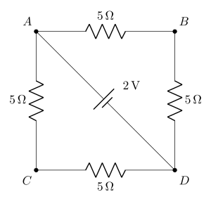
- AP EAPCET 2026Set eng-2026-05-13-FN1 markMCQQ.The potential difference between points A and B of the adjoining figure is: [FIGURE - a bridge-type resistor network: A connects to B via a 5Ω resistor and to C via a 5Ω resistor; B connects to D via a 5Ω resistor; C connects to D via two 5Ω resistors in series; a diagonal branch from A to D contains a 2V cell] (A) 32 V (B) 98 V (C) 34 V (D) 2 V
›Reveal solutionSolution
With the 2V cell across A–D, the resistor branches divide the voltage so the relevant potential difference is 34V.
The 2V cell sits in the diagonal A–D branch, so A and D are held at a fixed 2V apart. Take VA=2V, VD=0.
Two resistor paths connect A to D:
- A−B−D: 5Ω+5Ω=10Ω, carrying I1=102=0.2A.
- A−C−D: 5Ω+(5+5)Ω=15Ω, carrying I2=152A.
The node potentials (relative to D) are:
VB=I1(5)=1V,VC=I2(10)=152×10=34V. …
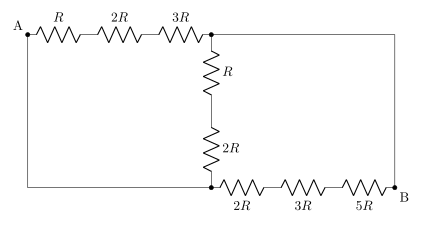
- AP EAPCET 2026Set eng-2026-05-14-AN1 markMCQQ.Effective resistance between A & B is ______, where R = 3 Ω [FIGURE: a resistor network — A connects through resistors R, 2R, 3R in series to a node N; N connects directly (by a plain wire) to B; N also connects through resistors R then 2R in series (a vertical branch) down to another node M; A also connects directly (by a plain wire) down to node M; M connects through resistors 2R, 3R, 5R in series to B] (A) 35Ω (B) 5Ω (C) 3Ω (D) 53Ω
›Reveal solutionSolution
The two "bypass" wires (no resistor) short two pairs of junctions together to the terminals, collapsing the network into three resistor chains all directly in parallel between A and B — giving Req=5R/3=5Ω.
Concept and Intuition
A plain wire (zero resistance) connecting two nodes forces them to the same potential — effectively merging them into a single node. Spotting these shorts first is the key simplification step; once the nodes are correctly merged, what looks like a complicated bridge-like network often collapses into simple series/parallel combinations.
Step-by-Step Solution
- Label the top-chain end node N (after A's top-path resistors R,2R,3R) and the bottom-chain start node M (after the middle vertical branch).
- The wire from N straight to B means N and B are the same node: N≡B.
- The wire from A straight down to M means A and M are the same node: A≡M.
- Now re-examine each resistor chain, which all effectively run directly between the (single) node A and the (single) node B:
- Top chain: R+2R+3R=6R (between A and N≡B) → directly between A and B.
- Middle vertical chain: R+2R=3R (between N≡B and M≡A) → also directly between A and B (just the opposite direction).
- Bottom chain: 2R+3R+5R=10R (between M≡A and B) → directly between A and B.
- All three chains (6R, 3R, 10R) are therefore in parallel between the same two terminals A and B: …
- AP EAPCET 2026Set eng-2026-05-18-FN1 markMCQQ.When two wires are connected in the two gaps of a meter bridge, the balancing point is obtained at a distance of 48.4 cm from the left end of the bridge wire. If the wire in the left gap is stretched so that its resistance increases by 3.2% and the wire in the right gap is stretched so that its length increases by 10%, then the new balancing length from the left end of the bridge wire is nearly (A) 33.3 cm (B) 66.6 cm (C) 44.4 cm (D) 55.5 cm
›Reveal solutionSolution
Meter-bridge balance ratio equals the resistance ratio; track how each resistance changes (a direct % change vs. a stretch, which changes R∝L2) and re-solve for the new balance point. Answer: 44.4 cm.
Concept and Intuition
In a meter bridge, RrightRleft=100−ll where l is the balancing length from the left. When a wire is stretched (not just its resistance quoted directly), its volume stays constant, so if its length grows by a factor (1+x), its cross-section shrinks by the same factor, and since R=ρL/A=ρL2/(Volume), resistance scales as L2 — a 10% length increase means resistance grows by (1.1)2=1.21×, not just 10%.
Step-by-Step Solution
- Initial ratio: R2R1=100−48.448.4=51.648.4.
- Left gap resistance increases by 3.2% (given directly): R1′=1.032R1.
- Right gap wire is stretched so its length grows by 10%; resistance scales as L2: R2′=(1.10)2R2=1.21R2. …
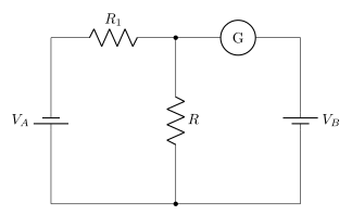
- AP EAPCET 2026Set ap-2026-05-19-AN1 markMCQQ.In the circuit shown, the cells A and B have negligible resistance. For VA=12V, R1=500Ω and R=100Ω, the galvanometer (G) shows no deflection. The value of VB is: [FIGURE] (a circuit where cell VA connects through resistor R1 to a node; from that node a galvanometer G connects onward to cell VB; a resistor R connects from the same node down to a common bottom wire that joins the negative terminals of VA, R, and VB, forming a bridge-like network) (A) 4V (B) 2V (C) 12V (D) 6V
›Reveal solutionSolution
The circuit is a Wheatstone bridge with batteries in place of resistors; zero galvanometer deflection means the voltage at the middle node is the same from both sides. Using voltage division, VB must be 2V, so the correct option is (B).
Concept & Intuition: Wheatstone Bridge Symmetry
When a galvanometer shows no deflection, it means no current flows through it. That can only happen if the two points it connects are at the same electric potential. In a standard Wheatstone bridge, we compare voltages across two resistor pairs. Here, the “resistors” are actually batteries and a single resistor, but the same principle applies: the voltage at the top-middle node (call it P) must be equal when measured from the left side (through R1 and VA) and from the right side (through VB directly). The bottom rail is the common reference (ground). So we simply compute VP from each side and set them equal.
Step-by-step solution
-
Identify the nodes and reference
Let the bottom wire be 0V (ground). The top-left node (positive terminal of VA) is at +12V. The top-right node (positive terminal of VB) is at VB (unknown). The middle node (between R1 and G) is P.
-
No deflection ⇒ no current through G
If G shows zero deflection, the current through it is zero. That means the voltage at P is the same whether you approach from the left or from the right. In other words, the potential difference across G is zero: VP(left)=VP(right).
-
Find VP from the left side
On the left, VA=12V is connected to P through R1=500Ω. Since no current flows through G, the only path from P to ground is through R=100Ω (down to the bottom rail). So R1 and R form a voltage divider between 12V and 0V:
VP=12V×R1+RR=12×500+100100=12×600100=12×61=2V.
- Find VP from the right side …
-
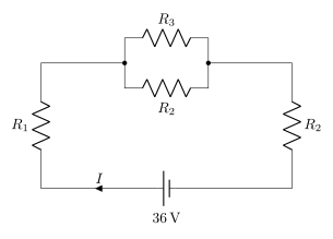
- AP EAPCET 2026Set eng-2026-05-18-AN1 markMCQQ.In the circuit shown in the figure, the current (I) is 6 A when R3 is infinite and current (I) is 9 A when R3 is short circuited. Then, the values of R1 and R2 are respectively [FIGURE] (a circuit with a 36V battery (current I) connected to two vertical resistors R1 (left) and R2 (right) at the outer edges; between them, in the middle, are two parallel horizontal branches, one containing resistor R3 and the other containing resistor R2) (A) 4Ω,2Ω (B) 2Ω,4Ω (C) 2Ω,2Ω (D) 1Ω,4Ω
›Reveal solutionSolution
Two current readings give R1+2R2=6Ω and R1+R2=4Ω, so R1=R2=2Ω.
Concept and Intuition
The current path is R1 in series with the parallel pair (R3∥R2mid) in series with the right-hand R2. When R3=∞ the parallel pair reduces to the middle R2; when R3=0 the parallel pair is a short and drops out. Each condition gives a simple series equation from Req=V/I.
Step-by-Step Solution
- With R3=∞: Req=636=6Ω=R1+R2mid+R2=R1+2R2.
- With R3=0: the middle branch is shorted, so Req=936=4Ω=R1+R2.
- Subtract: (R1+2R2)−(R1+R2)=6−4⇒R2=2Ω. …
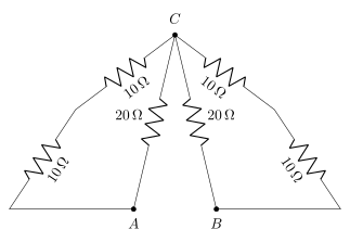
- AP EAPCET 2026Set ap-2026-05-20-FN1 markMCQQ.The equivalent resistance across AB of the circuit is [FIGURE] (a resistor network shaped like a folded triangle: an apex point C at the top connects via a 10Ω resistor down-left and a 10Ω resistor down-right to two upper corner points; the left upper corner connects via a 10Ω resistor down the outer left side to a bottom-left corner; the right upper corner connects via a 10Ω resistor down the outer right side to point B; two 20Ω resistors run diagonally, one from the left upper corner area down to point A and the other from the right upper corner area down to point B; points A and B lie next to each other at the bottom) (A) 20Ω (B) 10Ω (C) 80Ω (D) 40Ω
›Reveal solutionSolution
A symmetric resistor network folds into two identical branches from C to A and from C to B, each reducing to 10Ω by series-parallel combination, giving a total of 20Ω between A and B.
Concept and Intuition
When a network has left-right mirror symmetry about a central apex, we can analyze one half and double it (for the identical mirror half) rather than solving the whole bridge at once. Here, each side of the apex C offers two parallel routes down to its respective terminal — a direct 20Ω resistor and a 10Ω+10Ω series path through the upper corner node — and these combine identically on both sides.
Step-by-Step Solution
- On the left side: C connects to upper-left node P via 10Ω, and P connects on down to terminal A via 10Ω (through the outer left side), giving a series path C→P→A of 10+10=20Ω. C also connects directly to A via a 20Ω diagonal resistor. These two 20Ω paths are in parallel: (201+201)−1=10Ω.
- By the mirror symmetry of the network, the right side gives the same result: the effective resistance from C to B is also 10Ω. …
- AP EAPCET 2025Set eng-2025-05-23-FN1 markMCQQ.When a wire is connected in the left gap of a metre bridge, the balancing point is at 40 cm from the left end of the bridge wire. If the wire in the left gap is stretched so that its length is doubled and again connected in the same gap, then the balancing point from the left end of the bridge wire is (A) 11300 cm (B) 11800 cm (C) 11400 cm (D) 11700 cm
›Reveal solutionSolution
Stretching a wire to double its length quadruples its resistance (constant volume, R∝L2); reapply the meter-bridge balance condition with the new resistance.
Concept and Intuition
In a meter bridge, YX=100−ll where X is the unknown resistance in the left gap, Y the fixed resistance in the right gap, and l the balance length from the left end. When a wire is stretched, its volume V=AL stays constant, but A decreases as L increases. Since R=ρL/A=ρL2/(AL)=ρL2/V, resistance is proportional to L2: doubling the length quadruples the resistance.
Step-by-Step Solution
- Initial balance: l=40 cm, so YX=100−4040=6040=32.
- After stretching to double the length, volume is conserved, so X′=4X (since R∝L2 at constant volume).
- New ratio: YX′=4⋅YX=4⋅32=38.
- New balance point l′: YX′=100−l′l′⇒38=100−l′l′. …
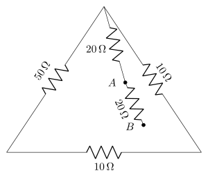
- AP EAPCET 2025Set ap-2025-05-19-AN1 markMCQQ.In the circuit of resistors shown in the figure, the effective resistance between points A and B is [FIGURE] (a triangular network of resistors: the left side of the triangle is a 50 Ω resistor; from the top vertex two 20 Ω resistors run down to two adjacent internal nodes labelled A and B; the right side of the triangle is a 10 Ω resistor connecting to the right vertex; the base of the triangle is a 10 Ω resistor) (A) 10 Ω (B) 320 Ω (C) 65 Ω (D) 15 Ω
›Reveal solutionSolution
The five resistors form a balanced Wheatstone bridge between A and B: the two 20 Ω arms and two 10 Ω arms give 1020=1020, so the 50 Ω bridge arm carries no current and RAB=(20+10)∥(20+10)=15 Ω -> option (D).
Read the network as a bridge with A and B the input terminals and two intermediate nodes P and Q:
- Arm A-P: 20 Ω, arm P-B: 10 Ω
- Arm A-Q: 20 Ω, arm Q-B: 10 Ω
- Bridge arm P-Q: 50 Ω
Balance condition.
RPBRAP=1020=2,RQBRAQ=1020=2. …
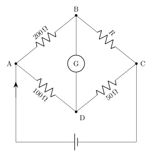
- AP EAPCET 2025Set ap-2025-05-20-FN1 markMCQQ.If the Wheatstone bridge shown in the figure is balanced, then the value of R is [FIGURE] (a Wheatstone bridge circuit: junction A connects to junction B through a 200 Ω resistor and to junction D through a 100 Ω resistor; junction B connects to junction C through a resistor R and junction D connects to junction C through a 50 Ω resistor; a galvanometer G is connected between B and D; a battery is connected across A and C through the outer loop) (A) 50 Ω (B) 200 Ω (C) 300 Ω (D) 100 Ω
›Reveal solutionSolution
This is a balanced Wheatstone bridge; applying the balance condition to the four arms gives R=100 Ω.
Concept and Intuition
In a balanced Wheatstone bridge, no current flows through the galvanometer, so the two nodes it connects (here B and D) are at the same potential. This means the potential drop from A to B equals the drop from A to D (in the appropriate ratio), and the same for the drops from B to C and D to C. This lets us relate the four resistances without needing to know the battery EMF.
Step-by-Step Solution
- Since the bridge is balanced, the currents through AB and BC are equal (call it I1, since no current diverts through the galvanometer at B), and the currents through AD and DC are equal (call it I2).
- Because VB=VD: the drop VA−VB (across the 200 Ω arm, current I1) equals the drop VA−VD (across the 100 Ω arm, current I2):
I1(200)=I2(100) ⇒ I2I1=21.
- Likewise VB−VC=VD−VC: the drop across arm BC (R, current I1) equals the drop across arm DC (50 Ω, current I2): I1R=I2(50). …
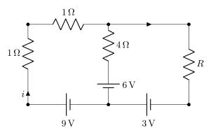
- AP EAPCET 2025Set ap-2025-05-20-FN1 markMCQQ.In the given circuit, if the current through 4 Ω resistor is zero, then the value of the resistance R is [FIGURE] (a circuit diagram: a 9 V battery at the bottom left is in series with a 1 Ω resistor, with current i flowing upward into a top-left node; from that node a 1 Ω resistor connects rightward, with a current arrow, to a second top node; from the first top-left node a branch goes down through a 4 Ω resistor in series with a 6 V battery to the bottom rail; from the second top node a branch goes down through a 3 V battery to the bottom rail, and further to the right another branch goes down through resistance R to the bottom rail; all the bottom nodes are connected along a common bottom wire) (A) 1 Ω (B) 2 Ω (C) 3 Ω (D) 4 Ω
›Reveal solutionSolution
Zero current in the 4 Ω branch turns the network into one series loop; combining the loop equation with the branch's zero-current voltage condition pins down R=2 Ω.
Concept and Intuition
When a branch of a network carries zero current, it does not affect the currents elsewhere in the circuit (Kirchhoff's current law lets us simply ignore it when tracing current paths) — but the voltage across that branch is still fixed by whatever component sits in it (here, purely by the 6 V battery's EMF, since there's no IR drop across the 4 Ω resistor when I=0). This gives an extra equation relating the potentials of the two nodes that branch connects to, on top of the main loop equation for the current that does flow.
Step-by-Step Solution
- Since the 4 Ω branch carries no current, the only current path is the outer loop: bottom-left node → 1 Ω → top-left node → 1 Ω → top-middle/top-right node → R → bottom-right node → 3 V battery → bottom-middle node → 9 V battery → bottom-left node. A single current i flows around this loop.
- Applying Kirchhoff's voltage law around this loop (resistive drops of 1+1=2Ω in series with R, balanced against the two battery EMFs in the bottom wire) gives one relation between i and R.
- The zero-current condition on the middle branch means the potential difference between the top-middle node and the bottom-middle node equals exactly the 6 V battery's EMF (no drop across the 4 Ω resistor since I=0 there). …
- AP EAPCET 2025Set eng-2025-05-27-FN1 markMCQQ.In a meter bridge, the null point is located at 20 cm from left end of the wire when resistances R and S are connected in the left and right gaps respectively. If the resistance S is shunted with 60 Ω resistance, the null point shifted by 5 cm, then the values of R and S are respectively (A) 24 Ω, 6 Ω (B) 6 Ω, 24 Ω (C) 5 Ω, 20 Ω (D) 20 Ω, 5 Ω
›Reveal solutionSolution
This tests the meter bridge (Wheatstone bridge) balance condition and how shunting one arm shifts the null point; the answer is (C) R=5 Ω, S=20 Ω.
Concept and Intuition
A meter bridge balances when SR=100−ll, where l is the balance length measured from the end where R is connected. Shunting S with an external resistor reduces its effective resistance; since R is unchanged, the ratio R/S increases, which forces the balance length l to increase (the null point moves toward the S side) to keep the bridge balanced.
Step-by-Step Solution
- Initial balance: l=20 cm, so SR=100−2020=8020=41, i.e. S=4R.
- Shunting S with 60 Ω makes the new resistance S′=S+60S×60<S, which increases the ratio R/S′, so the null point moves further from R's end: l′=20+5=25 cm.
- New balance condition: S′R=100−2525=7525=31⇒S′=3R.
- Also S′=4R+6060(4R)=4R+60240R. …
🎓Unlock everything free for 14 days
- ✓Full step-by-step solutions
- ✓Concept-first explanations
- ✓Methods, shortcuts & mistakes
- ✓PYQ mapping + timed mock tests
Full access for 14 days. No credit card required.