Q.(a) Obtain the expression for the magnetic energy stored in a solenoid in terms of magnetic field B, area A and length l of the solenoid.
🔒You're viewing a preview — the full solution, concept, methods & PYQ mapping are locked.
🔒 Start your 14-day free trial to unlock the full solution →Concept understanding — Magnetic Energy Density
Magnetic Energy Density
A magnetic field stores energy. Building up a current in an inductor requires work against the induced back-emf, and that work is stored in the field around it. The magnetic energy density is the energy stored per unit volume of the field.
Energy stored in an inductor
When the current in an inductor of self-inductance L grows, the induced back-emf is ε=−LdI/dt. The work done by the source to push charge dq=Idt against this emf is
dW=LIdI
Integrating from 0 to the final current I,
U=∫0ILIdI=21LI2
This energy is stored in the magnetic field of the inductor.
From inductor to field: the energy density
Take a long solenoid with n turns per unit length, cross-sectional area A and length l. Its self-inductance is L=μ0n2Al, and the field inside is B=μ0nI, so I=B/(μ0n). The stored energy becomes
U=21LI2=21(μ0n2Al)(μ0nB)2=2μ0B2(Al)
Since Al is the volume occupied by the field, the energy per unit volume is
uB=AlU=2μ0B2
uB=2μ0B2
Although derived for a solenoid, this result is general: wherever a magnetic field B exists, it carries an energy density B2/2μ0, measured in J/m3.
Comparison with the electric field
The electric field stores energy at density uE=21ε0E2. The magnetic analogue uB=B2/2μ0 has the same structure, and together they give the energy carried by electromagnetic waves. …
Why this formula?
Magnetic Energy Density
Building up a magnetic field costs work: as current rises, the induced back-emf (Lenz's law) opposes it, and you must push against that opposition. That work is not lost — it is stored in the magnetic field itself. Magnetic energy density uB is how much of this energy sits in each cubic metre of the field.
uB=2μ0B2(vacuum),uB=2μB2 (medium)
Deriving it from a solenoid
The energy stored in an inductor carrying current I is a standard result:
U=21LI2
For a long solenoid (n turns per unit length, area A, length l):
- Field inside: B=μ0nI
- Inductance: L=μ0n2Al
Substituting and eliminating I=B/(μ0n):
U=21(μ0n2Al)(μ0nB)2=2μ0B2(Al)
Since Al is exactly the volume V where the field lives, the energy per unit volume is:
uB=VU=2μ0B2
Equivalent forms, using B=μH, are uB=21μH2=21BH.
Why it makes sense …
Concept: Magnetic Energy Density — the energy per unit volume stored in a magnetic field is uB=2μ0B2.
(a) For a solenoid of length l, area A, and n turns per unit length, the self-inductance is L=μ0n2Al. The current I produces a uniform field B=μ0nI, so I=B/(μ0n). The stored magnetic energy is
UB=21LI2=21(μ0n2Al)(μ0nB)2=2μ0B2Al.
Since Al is the volume, this confirms UB=uB×volume. …
Magnetic energy stored in a solenoid is 2μ01B2Al, which is analogous to electrostatic energy 21ε0E2Ad in a capacitor — both are 21× (field constant) × (field squared) × (volume).
The key insight here is that energy in a magnetic field is distributed throughout the space where the field exists, just like energy in an electric field. For a solenoid, the field is nearly uniform inside and zero outside, so the energy density is constant over the volume Al. This lets us write total energy as (energy density) × (volume).
Let’s build this step by step.
- Start with the inductance of a solenoid. For a long solenoid of length l, cross-sectional area A, and N turns, the inductance is
L=μ0lN2A.
This comes from the flux linkage: L=NΦ/I, where Φ=BA and B=μ0(N/l)I.
- Energy stored in an inductor. The energy stored when a current I flows is
U=21LI2.
This is the standard result from integrating P=VI=LIdI/dt over time.
- Express I in terms of B. Inside the solenoid, B=μ0lNI, so
I=μ0NBl.
- Substitute into U=21LI2.
U=21(μ0lN2A)(μ0NBl)2.
Simplify stepwise:
U=21μ0lN2A⋅μ02N2B2l2=21μ0B2Al.
U=2μ01B2Al
Notice the N and l cancel beautifully — the result depends only on B, A, and l, not on the number of turns. That’s because B already encodes the effect of the current and geometry.
- Interpretation: magnetic energy density. The volume inside the solenoid is V=Al, so the energy per unit volume is
uB=VU=2μ0B2.
This is the magnetic energy density — a universal result for any magnetic field in vacuum, not just solenoids.
- Now compare with the electrostatic case. For a parallel-plate capacitor with plate area A, separation d, and electric field E between them, the capacitance is C=ε0A/d, and the stored energy is
UE=21CV2.
Using V=Ed, we get
UE=21(ε0dA)(Ed)2=21ε0E2Ad.
The volume between the plates is Ad, so the electrostatic energy density is
uE=21ε0E2.
The symmetry is striking: …
Method: Energy Density Approach
This method uses the magnetic energy density formula derived from the solenoid's self-inductance.
(a) Magnetic Energy in a Solenoid
Step 1: Recall the energy stored in an inductor
The energy stored in any inductor is:
U=21LI2
Step 2: Express L and I in terms of B
For a long solenoid:
- L=μ0n2Al (where n = turns per unit length)
- Magnetic field inside solenoid: B=μ0nI ⇒ I=μ0nB
Step 3: Substitute and simplify
U=21(μ0n2Al)(μ0nB)2
U=21μ0n2Al⋅μ02n2B2
U=2μ0B2⋅Al
Step 4: Write the final expression
Magnetic energy stored:
UB=2μ0B2⋅(Al)
Here, Al is the volume of the solenoid's interior.
(b) Comparison with Electrostatic Energy in a Capacitor
Parallel plate capacitor:
- Electric field: E=dV
- Energy stored: UE=21CV2
- Using C=dε0A and V=Ed:
UE=21ε0E2⋅(Ad)
Key comparison:
| Feature | Magnetic (Solenoid) | Electrostatic (Capacitor) |
|---------|-------------------|--------------------------| …
(a) Expression for Magnetic Energy Stored in a Solenoid
We start from the energy stored in an inductor:
U=21LI2
For a solenoid of length l, area A, and N turns:
- Inductance:
L=μ0lN2A
- Magnetic field inside:
B=μ0lNI⇒I=μ0NBl
Substitute L and I into U:
U=21(μ0lN2A)(μ0NBl)2
Simplify step-by-step:
U=21⋅μ0lN2A⋅μ02N2B2l2
Cancel N2, one l, and one μ0:
U=21⋅μ0B2⋅Al
Since Al is the volume of the solenoid:
U=2μ0B2⋅(volume)
Magnetic energy density (energy per unit volume):
uB=2μ0B2
(b) Comparison with Electrostatic Energy in a Capacitor
For a parallel plate capacitor (area A, separation d, electric field E):
- Capacitance:
C=dε0A
- Voltage:
V=Ed
- Energy stored:
U=21CV2=21ε0E2⋅(Ad)
So electrostatic energy density:
uE=21ε0E2
Key Comparison
| Aspect | Magnetic (solenoid) | Electrostatic (capacitor) |
|---|---|---|
| Energy density | uB=2μ0B2 | uE=21ε0E2 |
| Field | B (magnetic) | E (electric) |
| Constant | μ0 (permeability) | ε0 (permittivity) |
| Form | 21⋅μ0B2 | 21ε0E2 |
Both are quadratic in the field and proportional to volume. The constants μ0 and ε0 play symmetric roles.
Common Mistakes & How to Avoid Them
✗ Mistake 1: Forgetting the factor of 21
- Why it happens: Students rush and write U=LI2 or U=B2/μ0.
- How to avoid: Always start from U=21LI2 — the 21 comes from integrating P=VI from 0 to final current.
✗ Mistake 2: Wrong substitution for I in terms of B
- Why it happens: Using B=μ0nI but forgetting n=N/l.
- How to avoid: Write B=μ0lNI explicitly, then solve for I carefully.
✗ Mistake 3: Mixing up A and l in inductance formula
- Why it happens: L=μ0N2A/l — students swap A and l.
- How to avoid: Remember: L is proportional to area and inversely proportional to length. Draw the solenoid to visualize. …
- AP EAPCET 2026Set eng-2026-05-12-AN1 markMCQQ.A pure inductor of inductance 3 H (negligible resistance) is connected to a time-varying voltage source such that v(t)=4t volts. Here, t is in seconds. If the voltage is applied at t=0, calculate the energy stored in the inductor after 3 s. (A) 24 J (B) 36 J (C) 48 J (D) 54 J
›Reveal solutionSolution
Integrate v=Ldi/dt to find the current at t=3s (6 A), then use U=21Li2 to get 54 J.
Concept and Intuition
For a pure (resistanceless) inductor, the applied voltage sets the rate of change of current, not the current itself. So with a time-varying voltage we must integrate to find i(t) before we can use the energy formula U=21Li2, which only depends on the instantaneous current.
Step-by-Step Solution
- For an inductor, v(t)=Ldtdi, so dtdi=Lv(t)=34t.
- Integrate from t=0 (current starts at 0, since the voltage is applied at t=0): i(t)=∫0t34t′dt′=34⋅2t2=32t2.
- At t=3 s: i(3)=32×9=6 A. …
- AP EAPCET 2026Set eng-2026-05-18-FN1 markMCQQ.An inductor of inductance 5 henry is carrying an electric current of 4 mA. Then the energy stored in the inductor is (A) 50 μJ (B) 1000 μJ (C) 40 μJ (D) 20 μJ
›Reveal solutionSolution
Energy stored in a current-carrying inductor is U=21LI2. Answer: 40 μJ.
Concept and Intuition
An inductor stores energy in its magnetic field, analogous to how a capacitor stores energy in its electric field. The formula U=21LI2 comes from integrating the back-EMF work done in building up the current from zero to I.
Step-by-Step Solution
- L=5 H, I=4 mA=4×10⁻³ A.
- I2=(4×10⁻³)2=16×10−6 A2. …
- AP EAPCET 2025Set eng-2025-05-21-FN1 markMCQQ.If the magnetic field inside a solenoid is B, then the magnetic energy stored in it per unit volume is (c - speed of light in vacuum and ε0 is permittivity of free space) (A) ε0c2B2 (B) 2ε0c2B2 (C) 2ε0c2B2 (D) 4ε0c2B2
›Reveal solutionSolution
This tests the standard formula for magnetic energy density and its rewriting using c2=μ0ε01. Answer: 2ε0c2B2.
Concept and Intuition
Just as an electric field stores energy at density 21ε0E2, a magnetic field stores energy at density 2μ0B2 (this comes from the energy stored in an inductor's field, analogous to a capacitor's electric field energy). The relation c=μ0ε01 links the two constants and lets us re-express μ0 in terms of c and ε0.
Step-by-Step Solution
- Start with the magnetic energy density formula: uB=2μ0B2.
- From c2=μ0ε01, solve for μ0: μ0=ε0c21. …
- AP EAPCET 2025Set ap-2025-05-20-AN1 markMCQQ.The energy stored in a coil of inductance 50 mH carrying a current of 2 A is (A) 1 J (B) 0.1 J (C) 0.05 J (D) 0.5 J
›Reveal solutionSolution
A direct plug-in of the standard inductor energy-storage formula.
Concept and Intuition
An inductor stores energy in its magnetic field while carrying current, analogous to how a capacitor stores energy in its electric field. The stored energy is U=21LI2.
Step-by-Step Solution
- L=50mH=0.05 H, I=2 A. …
- AP EAPCET 2025Set eng-2025-05-23-AN1 markMCQQ.When a current of 4 mA passes through an inductor, if the flux linked with it is 32×10−6 Tm2, then the energy stored in the inductor is (A) 64×10−9 J (B) 32×10−9 J (C) 128×10−9 J (D) 96×10−9 J
›Reveal solutionSolution
This tests the two linked inductor relations Φ=LI and U=21LI2: first find L from the given flux and current, then use it to get the stored magnetic energy — 64×10−9 J.
Concept and Intuition
An inductor's defining property is that the flux linked with it is proportional to the current through it, Φ=LI, with L the self-inductance. Once L is known, the energy stored in the inductor's magnetic field for a given current follows the standard formula U=21LI2 — analogous to 21CV2 for a capacitor's electric field.
Step-by-Step Solution
- Find the inductance from Φ=LI: L=IΦ=4×10−332×10−6=8×10⁻³ H.
- Energy stored: U=21LI2=21(8×10⁻³)(4×10⁻³)2. …
- AP EAPCET 2024Set ap-2024-05-16-AN1 markMCQQ.A coil having 0.64 mH inductance and 0.8 Ω resistance connected to a battery of 12 V. The energy stored in the magnetic field created by that coil is (A) 32×10−3 J (B) 81×10−3 J (C) 64×10−3 J (D) 72×10−3 J
›Reveal solutionSolution
At steady state the inductor behaves like a plain resistor (no back-emf once current is constant); find I=V/R, then use U=21LI2 to get 72×10−3 J.
Concept and Intuition
Once a coil connected to a DC battery reaches steady state, the current no longer changes, so there is no induced back-emf (ε=−LdI/dt=0). The circuit behaves as a pure resistor, and the final steady current is simply I=V/R. The energy stored in the magnetic field of an inductor carrying current I is U=21LI2.
Step-by-Step Solution
- Steady-state current: I=RV=0.812=15 A.
- Energy stored: U=21LI2=21(0.64×10⁻³)(15)2. …
- AP EAPCET 2024Set eng-2024-05-18-FN1 markMCQQ.If the current through an inductor increases from 2 A to 3 A, the magnetic energy stored in the inductor increases by (A) 125% (B) 225% (C) 50% (D) 75%
›Reveal solutionSolution
Magnetic energy in an inductor scales with the square of the current; going from 2 A to 3 A raises the stored energy by 125%.
Concept and Intuition
The energy stored in an inductor is U=21LI2 — quadratic in current, so even a modest current increase can produce a large percentage jump in stored energy.
Step-by-Step Solution
- U1=21L(2)2=2L.
- U2=21L(3)2=4.5L. …
- AP EAPCET 2023Set eng-2023-05-17-FN1 markMCQQ.Physically, the self-inductance plays the role of (A) inertia (B) kinetic energy (C) potential energy (D) velocity
›Reveal solutionSolution
This tests the mechanical–electrical analogy for inductors: self-inductance resists change in current the way inertia resists change in velocity.
Concept and Intuition
An inductor doesn't oppose current itself — it opposes a change in current. By Faraday's/Lenz's law, whenever the current through an inductor tries to rise or fall, the inductor generates a back-emf that fights that change. This is conceptually identical to Newton's first law: a mass doesn't oppose velocity itself, it opposes a change in velocity (acceleration). This parallel is exactly why L is treated as the electrical analogue of mass in the standard LC-oscillator ↔ spring-mass analogy.
Step-by-Step Solution
- Induced emf in an inductor: ε=−Ldtdi.
- The negative sign (Lenz's law) means this emf always opposes the change in current, not the current itself.
- Compare with Newton's second law F=mdtdv — mass m is the measure of opposition to a change in velocity. …
- AP EAPCET 2021Set ap-2021-09-06-AN1 markMCQQ.Current in a coil with self-inductance 2 H is increasing according to I=(2sint2) ampere. Amount of energy spent during the period when current changes from 0 to 2A is ____ (A) 4 J (B) 6 J (C) 8 J (D) 12 J
›Reveal solutionSolution
This tests whether you know that inductor energy depends only on the current value, not its time-profile. The energy spent is 4 J.
Concept and Intuition
An inductor stores energy in its magnetic field, and that stored energy is a state function of the instantaneous current: U=21LI2. It doesn't matter that I=2sin(t2) is a complicated, non-uniformly increasing function of time — the source only ever has to supply enough energy to build up whatever magnetic field corresponds to the final current, minus what corresponds to the initial current. This is exactly analogous to gravitational PE depending only on height, not the path taken.
Step-by-Step Solution
- Energy stored in an inductor carrying current I: U=21LI2.
- Given: L=2 H, current changes from I1=0 to I2=2 A.
- Energy spent =U2−U1=21LI22−21LI12=21(2)(2)2−0=4 J.
Common Mistakes …
- AP EAPCET 2021Set ap-2021-09-06-FN1 markMCQQ.Two different coils have self inductance L1=8mH and L2=2mH. The current in one coil is increased at a constant rate. The current in the second coil is also increased at the same rate. At a certain instant of time, power given to both the coils is the same. At the time, the current, the induced voltage and the energy stored in the first coil are i1,v1 and w1 respectively. Corresponding values for the second coil at the same instant are i2,v2 and w2 respectively. Then find the value of w1w2= (A) w1w2=8 (B) w1w2=81 (C) w1w2=4 (D) w1w2=41
›Reveal solutionSolution
Equal instantaneous power (P=Lidi/dt) at the same di/dt forces L1i1=L2i2; converting that ratio into stored energies 21Li2 gives w2/w1=4.
Concept and Intuition
When current in an inductor changes at rate di/dt, the induced emf is v=Ldi/dt and the instantaneous power delivered is P=vi=Lidtdi. Because di/dt is identical for both coils, equal power at some instant directly constrains the product Li, not L or i alone.
Step-by-Step Solution
- Equate powers: L1i1(di/dt)=L2i2(di/dt)⇒L1i1=L2i2.
- So i1i2=L2L1=28=4.
- Energy stored in an inductor: w=21Li2. …
- AP EAPCET 2021Set ap-2021-10-05-FN1 markMCQQ.The currents in two coils of self-inductances 5 mH and 1 mH are increasing at the same rate at a certain instant. The power supplied to the coils is also same. Then identify the false statement among the following: (A) The ratio of induced emf's is 5 : 1 (B) The ratio of current in the coils is 1 : 5 (C) The ratio of energy stored in the two coils at that instant is 1 : 5 (D) The ratio of energy stored in the two coils at that instant is 9 : 25
›Reveal solutionSolution
Working through emf, current, and energy ratios from L1=5mH, L2=1mH with equal dI/dt and equal power shows the energy ratio is actually 1:5, so the "9:25" statement (D) is the false one.
Concept and Intuition
Three quantities are linked here — induced emf (ε=LdI/dt), power (P=εI), and stored energy (U=21LI2) — and each ratio must be derived consistently from the given constraints (same dI/dt, same power) rather than assumed independently.
Step-by-Step Solution
- Same dI/dt=k for both coils, so ε1=L1k, ε2=L2k, giving ε1:ε2=L1:L2=5:1 — matches (A).
- Equal power: ε1I1=ε2I2⇒L1I1=L2I2⇒I1:I2=L2:L1=1:5 — matches (B).
- Energy stored: U=21LI2, so U2U1=L2L1(I2I1)2=5×(51)2=5×251=51.
- So U1:U2=1:5 — this matches (C), and directly contradicts (D)'s claim of 9:25. …
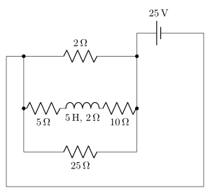
- AP EAPCET 2021Set eng-2021-08-24-FN1 markMCQQ.In the given circuit, find the energy stored in the coil at steady state. [FIGURE] (a circuit with a 25 V battery at the top right in series with a resistor network: a 2 Ω resistor forms the top branch connecting the left side to the battery's positive terminal; in parallel below it, between an inner-left node and an inner-right node, are a 5 Ω resistor and a 5 H, 2 Ω inductor coil; a 10 Ω resistor connects the inner-right node to the right branch leading to the battery; a 25 Ω resistor connects the bottom of the 5 Ω/coil branch to the bottom of the 10 Ω branch) (A) 2.13 J (B) 21 J (C) 0 J (D) 213 J
›Reveal solutionSolution
The circuit is a balanced Wheatstone bridge (2:5=10:25) with the coil sitting in the bridge arm,
so zero current ever flows through it and the stored energy is 0 J.
Concept and Intuition
Before grinding through node equations, it always pays to check whether a resistor network is secretly
a Wheatstone bridge, because a balanced bridge carries zero current through its bridge
(galvanometer) element — independent of that element's own resistance, and independent of the source
voltage. The balance condition for a bridge with arms R1,R2 (from the source's one terminal) and
R3,R4 (continuing to the other terminal) is
R2R1=R4R3.
Here the four resistors are 2Ω, 5Ω, 10Ω, 25Ω, with the coil bridging
the two mid-points — exactly the bridge topology.
Step-by-Step Solution
- Identify the four arms of the bridge: 2Ω and 5Ω leave the battery's node and go to the two bridge mid-points; 10Ω and 25Ω continue from those mid-points back to the battery's other node. The coil (5 H, 2 Ω) bridges the two mid-points.
- Check the balance ratio: 52=0.4 and 2510=0.4. Since these ratios are equal, the bridge is balanced.
- In a balanced bridge, both mid-points sit at exactly the same potential (regardless of the source …
🎓Unlock everything free for 14 days
- ✓Full step-by-step solutions
- ✓Concept-first explanations
- ✓Methods, shortcuts & mistakes
- ✓PYQ mapping + timed mock tests
Full access for 14 days. No credit card required.