Q.A parallel plate capacitor with air between the plates has a capacitance of 8 pF (1 pF=10−12 F). What will be the capacitance if the distance between the plates is reduced by half, and the space between them is filled with a substance of dielectric constant 6?
🔒You're viewing a preview — the full solution, concept, methods & PYQ mapping are locked.
🔒 Start your 14-day free trial to unlock the full solution →Concept understanding — Dielectric Insertion Capacitance
Dielectric Insertion Capacitance – From Intuition to Precision
Imagine you have two metal plates facing each other, separated by air. You connect them to a battery. The plates get charged — one positive, one negative — and they store energy in the electric field between them. That's a capacitor.
Now, without disconnecting the battery, you slide a slab of some insulating material (like glass, plastic, or mica) between the plates. What happens? The battery pushes more charge onto the plates. The capacitor now stores more charge for the same voltage. Its capacitance has increased.
That increase — the extra capacitance contributed by the presence of the dielectric — is what we call dielectric insertion capacitance.
The word "insertion" here simply means "the capacitance that appears because you inserted a dielectric." It's not a separate device; it's the change in capacitance due to the material.
Why does the capacitance increase?
The key is polarisation. Inside a dielectric, molecules are like tiny electric dipoles — they have a positive end and a negative end. In an electric field, these dipoles rotate to align with the field. The positive ends point toward the negative plate, and the negative ends point toward the positive plate.
This alignment creates a layer of bound charge on the surfaces of the dielectric, right next to the plates. This bound charge partially cancels the electric field inside the dielectric. But here's the crucial point: if the capacitor is connected to a battery (constant voltage), the battery responds by pushing more free charge onto the plates to restore the original field. More charge for the same voltage means higher capacitance.
If the capacitor is disconnected from the battery (constant charge), the dielectric reduces the voltage across the plates. Same charge, lower voltage — again, higher capacitance.
A common mistake: thinking the dielectric "creates" extra charge out of nothing. It doesn't. The battery supplies the extra charge in the constant-voltage case. In the constant-charge case, the voltage drops — the capacitance formula C=Q/V still gives a larger C because V is smaller.
The precise statement
Let’s define:
- C0 = capacitance of the capacitor with vacuum (or air) between the plates.
- κ (or εr) = dielectric constant (relative permittivity) of the material. For vacuum, κ=1. For most solids, κ>1 (e.g., glass ~5–10, water ~80).
When you fill the entire space between the plates with a dielectric of constant κ, the new capacitance is:
C=κC0
The dielectric insertion capacitance is the additional capacitance contributed by the dielectric:
Cinsertion=C−C0=(κ−1)C0
Cinsertion=(κ−1)C0
This is the extra capacitance you get purely because you inserted the dielectric. If κ=1 (vacuum), Cinsertion=0 — no insertion effect.
What if the dielectric only partially fills the gap?
In real problems, the slab might not fill the entire space. Then the capacitor behaves like two capacitors in series (or parallel, depending on geometry). The insertion capacitance is no longer a simple multiple — you have to compute the effective capacitance using the appropriate combination rules.
But the core idea remains: the dielectric increases capacitance because its polarisation reduces the net field (or, equivalently, allows more charge at the same voltage).
For a parallel-plate capacitor with plate area A, separation d, and a dielectric of thickness t inserted (leaving an air gap of d−t), the effective capacitance is:
C=d−t+κtε0A …
Concept: Dielectric Insertion Capacitance — capacitance depends on both geometry and the dielectric constant K.
Step 1 — Original capacitance
With air (K=1), C0=dε0A=8 pF.
Step 2 — New distance
Distance is halved: d′=d/2.
If only distance changed, capacitance would double: C1=d/2ε0A=2C0=16 pF. …
The capacitance increases due to two simultaneous changes: halving the plate separation doubles the capacitance, and inserting a dielectric of constant 6 multiplies it by 6. The combined effect gives a final capacitance of 96 pF.
The key idea here is that capacitance depends on geometry and the material between the plates. For a parallel plate capacitor, the formula is:
C=dε0εrA
where ε0 is the permittivity of free space, εr is the dielectric constant (relative permittivity), A is the plate area, and d is the separation.
When you change d or εr, the capacitance changes proportionally. Let’s walk through the problem step by step.
- Start with the initial conditions. The capacitor has air between its plates, so εr=1 (air’s dielectric constant is essentially 1). The initial capacitance is given as C1=8 pF. So we have:
C1=dε0A=8 pF
- Now apply the first change: distance is halved. The new distance is d′=d/2. If nothing else changed, the capacitance would become:
Cafter distance change=d/2ε0A=2⋅dε0A=2×8 pF=16 pF
Halving the separation doubles the capacitance — this makes intuitive sense because the plates are closer, so the electric field is stronger for the same charge, allowing more charge storage.
- Then apply the second change: insert a dielectric with εr=6. The dielectric fills the entire space between the plates. This multiplies the capacitance by the dielectric constant: …
Method: Combining a Geometry Change with a Dielectric Insertion
This method finds the new capacitance of a parallel plate capacitor when both the plate separation and the medium between the plates change at the same time.
Steps
Step 1: Start from the general parallel-plate formula
C=dε0εrA
Identify which of d and εr (the dielectric constant, =1 for air/vacuum) is changing, and by what factor.
Step 2: Apply the geometry change first, in isolation
Since C∝1/d, scaling d by some factor scales C by the reciprocal — this step doesn't involve the dielectric at all, so don't mix it with Step 3.
Step 3: Apply the dielectric change, multiplicatively …
Showing the 12 most recent of 27 on this concept.
- AP EAPCET 2026Set eng-2026-05-12-AN1 markMCQQ.A parallel plate capacitor of plate area 3A and plate separation 3d is filled with three dielectric slabs with dielectric constants K1=2, K2=4 and K3=6 as shown in the figure. The capacitance of the capacitor is (Figure: a parallel plate capacitor with total plate separation 3d and total plate area 3A. Dielectric K1 fills the left region of thickness d across the entire plate area 3A. The remaining thickness 2d (to the right) is divided along the area into two parts: the upper part, of area 2A, is filled with dielectric K2; the lower part, of area A, is filled with dielectric K3.) (A) 13d42Aϵo (B) 7d54Aϵo (C) 13d54Aϵo (D) 7d32Aϵo
›Reveal solutionSolution
One dielectric fills a full-area layer of thickness d (in series with the rest); the remaining 2d is split by area into two dielectrics side by side (in parallel with each other). Combine parallel first, then series with the first layer, to get C=13d42Aϵ0.
Concept and Intuition
When a capacitor is sliced by a plane parallel to the plates, the two slices behave as capacitors in series (same charge flows through, different fields in each layer). When a capacitor is divided by a plane perpendicular to the plates (side by side, same thickness), the two parts behave as capacitors in parallel (same voltage across each, charges add). Here the top-to-bottom split (K1 vs. the K2/K3 layer) is a series split; the left-right split within the lower 2d layer (K2 vs K3) is a parallel split.
Step-by-Step Solution
- K1 region: full area 3A, thickness d: C1=dK1ϵ0(3A)=d2ϵ0(3A)=d6ϵ0A.
- K2 region: area 2A, thickness 2d: C2=2dK2ϵ0(2A)=2d4ϵ0(2A)=d4ϵ0A.
- K3 region: area A, thickness 2d: C3=2dK3ϵ0(A)=2d6ϵ0A=d3ϵ0A. …
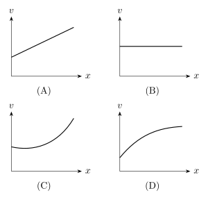
- AP EAPCET 2026Set eng-2026-05-13-FN1 markMCQQ.A parallel plate capacitor with dielectric is charged completely and the battery is then disconnected. Now if the dielectric is slowly pulled out of the capacitor then the variation of the potential(v) of the capacitor with respect to the length(x) of the dielectric pulled out is represented by (A) [FIGURE: V–x graph — a straight line of positive slope; V starts at a positive value at x = 0 and increases linearly as x increases] (B) [FIGURE: V–x graph — a horizontal straight line; V stays constant at a positive value as x increases] (C) [FIGURE: V–x graph — a curve that starts at a positive V, dips slightly to a shallow minimum, and then rises, curving upward increasingly steeply as x increases] (D) [FIGURE: V–x graph — a curve that starts at a positive V and rises smoothly and continuously with x, the value of V increasing throughout as x increases]
›Reveal solutionSolution
At constant charge, C decreases linearly as the dielectric is withdrawn, so V = Q/(C0 - kx) is a concave-up, accelerating curve (option C).
Concept and Intuition
Once the battery is disconnected the charge Q is trapped on the plates and stays constant. A partially inserted dielectric behaves like two capacitors in parallel: the still-covered part (permittivity K) and the exposed air part. As the dielectric is pulled out by length x, the high-permittivity area shrinks and the air area grows, so the total capacitance falls. With Q fixed, V = Q/C means the voltage rises as C falls.
Step-by-Step Solution
- Model the plate (length L, width w, separation d) as two parallel capacitors. After pulling out length x: C(x) = (epsilon0 w/d)[K(L - x) + x] = (epsilon0 w/d)[KL - (K - 1)x].
- So C decreases linearly with x: C(x) = C0 - k x, where C0 = (epsilon0 w/d)KL and k = (epsilon0 w/d)(K - 1) > 0.
- Charge is constant, so V = Q/C = Q / (C0 - k x).
- At x = 0, V = Q/C0, a positive intercept (not zero) — matching all four graphs starting above the origin.
- Slope: dV/dx = Qk / (C0 - k x)^2, which is positive and grows as x increases (denominator shrinks). Hence V rises with increasing steepness — concave up, accelerating.
- This matches the concave-up, increasingly-steep curve (option C), not the straight line (A), the flat line (B), or the saturating concave-down curve (D).
Common Mistakes …
- AP EAPCET 2026Set eng-2026-05-15-AN1 markMCQQ.In a parallel plate capacitor, each plate cross-sectional area is A and distance between plates is d. If a dielectric slab of area A, thickness 43d and dielectric constant 3 is placed between the parallel plates of the capacitor, then the new capacitance will be _____ times the initial capacitance (A) 21 (B) 31 (C) 3 (D) 2
›Reveal solutionSolution
A partially-filled parallel-plate capacitor (dielectric slab covering full plate area but only part of the gap) is modeled as two capacitors in series — the dielectric-filled section and the remaining air gap. Here both series capacitances turn out equal, giving a clean overall factor of 2. Answer: 2 times C0.
Concept and Intuition
When a dielectric slab of the same cross-sectional area as the plates but less than the full gap thickness is inserted, the capacitor behaves as two capacitors stacked in series along the field direction: one region has the dielectric (thickness t, constant K), and the remaining region (d−t) is air. This is because the electric displacement/charge is the same all the way across (series-like, same "current" of field lines through both), while the potential drops add up across the two regions — exactly the signature of a series combination. Each region individually is just a simple parallel-plate capacitor with its own thickness playing the role of "plate separation."
Step-by-Step Solution
- Original (no dielectric) capacitance: C0=dε0A.
- Dielectric-filled region: thickness t=43d, dielectric constant K=3:
C1=tKε0A=3d/43ε0A=3d3ε0A×4=d4ε0A=4C0
- Remaining air gap: thickness d−t=4d: C2=d/4ε0A=d4ε0A=4C0 …
- AP EAPCET 2026Set ap-2026-05-19-FN1 markMCQQ.When dielectric is inserted between the plates of a capacitor with battery connected, energy increases because of (A) increase in charge (B) increase in voltage (C) increase in field (D) increase in separation between the plates
›Reveal solutionSolution
Tests understanding of the battery-connected (constant-voltage) case for a capacitor with a dielectric — voltage stays fixed, capacitance and charge rise, and energy grows because of the extra charge the battery pushes in.
Concept and Intuition
There are two classic capacitor-with-dielectric scenarios, and they behave oppositely: if the capacitor is isolated (charge fixed), inserting a dielectric drops the voltage and the stored energy decreases. But if the battery stays connected (voltage fixed), the battery does extra work pushing more charge onto the plates as capacitance rises, and the stored energy increases — driven by that extra charge, not by any change in voltage (which the battery holds constant by definition).
Step-by-Step Solution
- With the battery connected, V across the capacitor is fixed by the battery (that's what "battery connected" means) — it cannot increase.
- Inserting a dielectric of constant K>1 raises the capacitance: C→C′=KC.
- Since Q=CV and V is unchanged, the charge rises: Q′=C′V=KCV=KQ>Q.
- Stored energy U=21QV (equivalently 21CV2); with V fixed and Q risen to KQ, U′=21(KQ)V=KU>U — energy increases. …
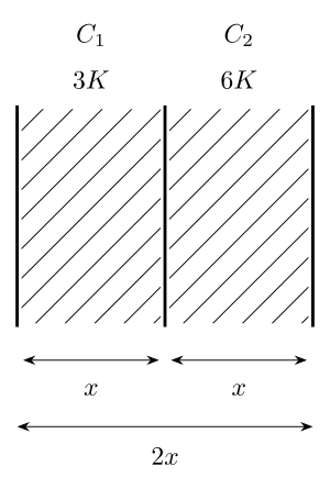
- AP EAPCET 2026Set eng-2026-05-18-AN1 markMCQQ.As shown in the figure two capacitors C1 & C2 each having same gap between the plates x filled with different media of dielectric constants 3K and 6K respectively. If these two capacitors are connected to a battery, the ratio of potential differences across dielectric layers of C1 and C2 is [FIGURE] (two adjoining parallel-plate capacitors C1 and C2 sharing a common middle plate; each capacitor's plate gap is x (combined width 2x); C1's gap is filled with a dielectric of constant 3K, and C2's gap is filled with a dielectric of constant 6K) (A) 2 (B) 6 (C) 4 (D) 8
›Reveal solutionSolution
Two capacitors sharing a middle plate are in series, so they carry equal charge; the potential drop across each is inversely proportional to its capacitance, giving a ratio of 2.
Concept and Intuition
When two parallel-plate capacitors share a common (floating) middle plate and the outer plates connect to the battery, the arrangement is electrically a series combination: the same charge Q flows through both. Since V=Q/C for each capacitor at fixed Q, whichever capacitor has the smaller capacitance ends up with the larger potential difference across it.
Step-by-Step Solution
- Both capacitors have identical geometry (same gap x, same plate area A), differing only in dielectric constant: C1=xε0(3K)A, C2=xε0(6K)A.
- Since the two capacitors share the middle plate, they are in series and carry the same charge Q. …
- AP EAPCET 2026Set ap-2026-05-20-AN1 markMCQQ.A parallel plate capacitor charged and disconnected from the battery then a dielectric is inserted between the plates of the capacitor. The energy of capacitor (A) Increases (B) decreases (C) remains same (D) zero
›Reveal solutionSolution
Charge is conserved once the battery is removed, so the relevant energy formula is U=Q2/(2C); since C increases with the dielectric, U falls.
Concept and Intuition
A parallel plate capacitor's energy can be written two ways: U=21CV2 (useful when voltage is fixed, i.e. still connected to a battery) or U=2CQ2 (useful when charge is fixed, i.e. isolated). After the battery is disconnected, the capacitor is an isolated system — no external circuit can change Q. So Q is the conserved quantity here, and we must use U=Q2/2C.
Step-by-Step Solution
- Before inserting the dielectric: capacitance C0, charge Q (fixed after disconnection), energy U0=2C0Q2.
- Insert a dielectric of constant K>1: new capacitance C=KC0.
- Charge Q cannot change (isolated system), so new energy U=2KC0Q2=KU0.
- Since K>1, U<U0 — the energy decreases. …
- AP EAPCET 2025Set eng-2025-05-21-FN1 markMCQQ.A capacitor of capacitance 2μF is charged to 50 V and then disconnected from the source. Later the gap between the plates of the capacitor is filled with a dielectric material. If the energy stored in the capacitor is decreased by 25% of its initial value, then the dielectric constant of the dielectric material is (A) 32 (B) 34 (C) 43 (D) 23
›Reveal solutionSolution
This tests energy stored in an isolated (disconnected) capacitor as a dielectric is inserted. Answer: K=34.
Concept and Intuition
Once a charged capacitor is disconnected from its source, its charge Q is fixed (nowhere for charge to go). Inserting a dielectric of constant K multiplies the capacitance by K: C′=KC. Since U=2CQ2 with Q fixed, increasing C by K decreases the stored energy by the same factor K — energy is not conserved here because work is done pulling the dielectric in (or released as the field does work on it).
Step-by-Step Solution
- Initial energy: Ui=2CQ2.
- After the dielectric is inserted: C′=KC, so Uf=2KCQ2=KUi.
- Given: energy decreases by 25%, so Uf=0.75Ui.
- Therefore KUi=0.75Ui⇒K=0.751=34. …
- AP EAPCET 2025Set eng-2025-05-21-AN1 markMCQQ.The radii of the inner and outer spheres of a spherical capacitor are 8 cm and 9 cm respectively. The outer sphere is earthed and the inner sphere is charged. If the space between the concentric spheres is filled with a liquid of dielectric constant 5, the capacitance of the capacitor is (A) 400 pF (B) 40 pF (C) 400 μF (D) 40 μF
›Reveal solutionSolution
Applying the spherical-capacitor formula with a dielectric filling the gap between the 8 cm and 9 cm radii spheres gives a capacitance of exactly 400 pF.
Concept and Intuition
A spherical capacitor consists of two concentric conducting spherical shells; the field exists only in the gap between them (zero inside the inner sphere and outside the outer, by Gauss's law, since the outer sphere is earthed). Filling that gap with a dielectric of constant K increases the capacitance by that same factor K compared to vacuum, because the dielectric weakens the field for a given charge, allowing more charge to be stored per unit potential difference.
Step-by-Step Solution
- Capacitance of a spherical capacitor (vacuum): C0=4πε0b−aab, where a = inner radius, b = outer radius.
- With dielectric of constant K filling the gap: C=4πε0Kb−aab=9×10⁹K×b−aab (using 4πε01=9×10⁹ SI).
- Convert: a=8cm=0.08 m, b=9cm=0.09 m, so ab=0.0072 m2 and b−a=0.01 m. …
- AP EAPCET 2025Set ap-2025-05-19-FN1 markMCQQ.To decrease the capacitance of a parallel plate capacitor (A) a dielectric material is to be introduced between the plates (B) the area of the plates is to be increased (C) the area of the plates is to be increased and distance between them is to be decreased (D) the distance between the plates is to be increased
›Reveal solutionSolution
Since C∝A/d (times εr for any dielectric present), capacitance decreases only when the separation d is increased (or the area is decreased, or a dielectric removed) — introducing a dielectric or increasing area both increase C.
Concept and Intuition
The parallel plate capacitor formula C=dε0εrA shows C is directly proportional to plate area A and dielectric constant εr, and inversely proportional to plate separation d. To decrease C, we must either shrink A, shrink εr (remove/weaken a dielectric), or grow d.
Step-by-Step Solution
- C=dε0εrA.
- Introducing a dielectric increases εr, so option (A) increases C — wrong direction.
- Increasing area A (option B) increases C — wrong direction.
- Increasing area while decreasing distance (option C) increases C on both counts — wrong direction. …
- AP EAPCET 2025Set eng-2025-05-24-FN1 markMCQQ.A parallel plate capacitor has plates of area 0.4π m2 and spacing of 0.5 mm. If a slab of thickness 0.5 mm and dielectric constant 4.5 is introduced in between the plates of the capacitor, then the capacitance of the capacitor is (A) 100 nF (B) 60 pF (C) 100 pF (D) 60 nF
›Reveal solutionSolution
Because the dielectric slab fills the entire gap, the capacitor's capacitance is simply Kε0A/d; this evaluates to 100 nF.
Concept and Intuition
When a dielectric slab of thickness t less than the full gap d is inserted, the effective capacitance formula has an air-gap term (d−t) and a dielectric term t/K added in series. But when t=d (the slab exactly fills the gap, as here — both are 0.5 mm), that air-gap term vanishes and the capacitor behaves exactly like a parallel-plate capacitor entirely filled with the dielectric: C=dKε0A.
Step-by-Step Solution
- Note slab thickness =0.5mm= full plate spacing d, so the dielectric fills the whole gap.
- Use C=dKε0A with K=4.5, A=0.4π m2, d=5×10⁻⁴ m.
- First find C0=dε0A=5×10−48.85×10−12×0.4π≈2.224×10⁻⁸ F (the capacitance without dielectric). …
- AP EAPCET 2025Set eng-2025-05-26-FN1 markMCQQ.If a dielectric slab of dielectric constant 3 is introduced between the plates of a capacitor having electric field 1.5π NC−1, then the electric displacement is (A) 125×10−12 Cm−2 (B) 125×10−9 Cm−2 (C) 250×10−12 Cm−2 (D) 250×10−9 Cm−2
›Reveal solutionSolution
This tests the relation between electric displacement, permittivity, dielectric constant, and the field inside a dielectric, D=ε0KE, giving 125×10−12Cm−2.
Concept and Intuition
The electric displacement field D relates to the free charge alone and is connected to the actual field E inside a linear dielectric medium by D=ε0KE=εE, where ε=ε0K is the medium's permittivity. Unlike E, which is reduced by the dielectric, D stays tied to the free surface charge density and can be obtained directly once K and E (in the dielectric) are known.
Step-by-Step Solution
- Given: K=3, E=1.5πNC−1.
- D=ε0KE=(8.85×10⁻¹²)(3)(1.5π).
- (8.85×10⁻¹²)(3)=26.55×10⁻¹². …
- AP EAPCET 2024Set ap-2024-05-16-FN1 markMCQQ.A parallel plate capacitor has two square plates of side 5 cm separated by 15 mm. A pyrex glass slab of dielectric constant K=4.5 and thickness 10 mm is placed between the plates. The capacitance of the capacitor is (A) 3.11×10⁻¹² F (B) 311 μF (C) 311 PF (D) 3.11 nF
›Reveal solutionSolution
This tests the formula for capacitance when a dielectric slab only partially fills the gap between the plates — the slab's thickness effectively shrinks by a factor of K in the "equivalent vacuum gap" calculation.
Concept and Intuition
When a dielectric slab of thickness t (less than the full plate separation d) is inserted, it's equivalent to replacing that slab with a vacuum gap of thickness t/K (since the dielectric increases capacitance, it behaves as if it were a "thinner" vacuum gap). The remaining vacuum gap (d−t) stays as is. Adding these gives an effective total separation to use in the ordinary parallel-plate formula C=ε0A/deff.
Step-by-Step Solution
- Plate side =5 cm =0.05 m, so area A=(0.05)2=2.5×10⁻³ m2.
- Total separation d=15 mm =0.015 m; dielectric thickness t=10 mm =0.01 m; remaining air gap =d−t=0.005 m.
- Effective separation: deff=(d−t)+Kt=0.005+4.50.01=0.005+0.00222=0.00722 m. …
🎓Unlock everything free for 14 days
- ✓Full step-by-step solutions
- ✓Concept-first explanations
- ✓Methods, shortcuts & mistakes
- ✓PYQ mapping + timed mock tests
Full access for 14 days. No credit card required.