Computer Science · Ch 1 — Computer System
Data Transfer between Memory and CPU
Data Transfer between Memory and CPU
Processing constantly moves data around inside a computer: between the CPU and primary memory, and between primary and secondary memory. The physical pathways that carry this traffic are called buses — sets of physical wires connecting the components. A bus carries data, for example, between a USB port and the hard disk, or between the hard disk and main memory.
The three types of bus
A bus system has three distinct types of bus, each with its own job:
- Data bus — transfers the actual data between components.
- Address bus — carries addresses from the CPU to main memory. The address of the memory location that the CPU wants to read from or write to is placed on the address bus.
- Control bus — carries control signals (such as "read" or "write") between components.
Together, these three buses make up the system bus, shown in Figure 1.8 connecting the CPU, memory, and input/output.
Directions: which buses are one-way?
- The data bus is bidirectional — the CPU may need to read data from main memory or write data to it, so data must be able to flow both ways.
- The address bus and control bus are unidirectional — the CPU issues addresses and control signals; memory does not send addresses back.
This is a favourite exam question: why is the data bus bidirectional while the address bus is unidirectional? Because data flows both to and from the CPU, but only the CPU specifies addresses.
How a memory transfer actually happens
The CPU interacts directly only with main memory — so any data coming from an input device, or any data on the hard disk, must first be placed in main memory before it can be processed. The transfer between CPU and main memory then uses the buses like this:
Common to both operations:
- The CPU places on the address bus the address of the main-memory location it wants to access.
- While executing the instruction, the CPU asserts the read or write control signal on the control bus.
Write operation:
- The CPU places the data on the data bus. …
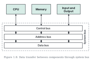
Drawn by us to help you understand the concept clearly, and verified to make sure it's accurate. For exams, practice from your NCERT textbook's own diagram.
Figure 1.8 shows how the major components of a computer talk to each other over the system bus. Across the top of the diagram sit three boxes — CPU, Memory, and Input and Output — the three parties that must constantly exchange information.
Below them, a dashed rectangle labelled "System bus" (the label written in rotated text along its right edge) encloses three stacked horizontal bars, one for each type of bus:
- the Control bus on top — carrying control signals such as read and write commands;
- the Address bus in the middle — carrying the memory addresses the CPU wants to access;
- the Data bus at the bottom — carrying the actual data.
Vertical double-headed arrows drop from each of the three top components down to the bus bars: the CPU, the Memory, and the Input/Output block each connect to the Control bus, the Address bus and the Data bus. The dashed outline makes the point that the three buses are not independent wires to separate places but one collective highway — together they make up the system bus that every component plugs into. …