Q.Two long and parallel straight wires A and B carrying currents of 8.0 A and 5.0 A in the same direction are separated by a distance of 4.0 cm. Estimate the force on a 10 cm section of wire A.
🔒You're viewing a preview — the full solution, concept, methods & PYQ mapping are locked.
🔒 Start your 14-day free trial to unlock the full solution →Concept understanding — Magnetic Force on Current
Magnetic Force on Current
Imagine a garden hose spraying pure water — bring a magnet near the stream and nothing happens, because water is electrically neutral. But if that stream carried electric charge (a current), the magnet would push the whole stream sideways. That is the essence of this concept: a current-carrying wire placed in a magnetic field experiences a sideways force, because every moving charge inside the wire feels the Lorentz force, and since the charges cannot leave the wire, they drag the wire along with them.
From a single charge to a wire
A single charge q moving with velocity v in a field B feels F=q(v×B). A current is just many such charges drifting together, so summing their individual forces over the whole wire gives a net force on it.
The metal lattice itself is neutral and stationary — only the free electrons drift. The magnetic force acts on those drifting electrons, which then collide with the lattice and transfer the push to the entire wire.
The formula
For a straight wire of length L carrying current I in a uniform field B:
F=I(L×B),F=ILBsinθ
where L points along the current and θ is the angle between the wire and B.
The force is zero when the wire runs parallel to the field (θ=0∘ or 180∘) and maximum when perpendicular (θ=90∘) — the magnetic force only responds to the component of current motion that is perpendicular to B.
Direction: the right-hand rule
Point your index finger along the current (L), your middle finger along the field (B); your thumb then gives the force direction — this is just the cross product L×B read off by hand. Because it is a cross product, swapping the two vectors reverses the force.
Worked example
A 0.5 m wire carries 3 A from east to west, in a uniform field of 0.2 T pointing north.
- θ=90∘ (the wire and the field are perpendicular), so F=ILBsinθ=(3)(0.5)(0.2)(1)=0.3 N. …
Concept: Magnetic Force Between Parallel Currents
Parallel currents in the same direction attract each other. The force per unit length between two long straight wires is given by:
LF=2πdμ0I1I2
Step 1 – Identify the given values
I1=8.0 A, I2=5.0 A, d=4.0 cm=0.040 m, L=10 cm=0.10 m, and μ0=4π×10−7 N/A2.
Step 2 – Calculate force per unit length
LF=2π(0.040)(4π×10−7)(8.0)(5.0)=2π×0.0404π×10−7×40=2×0.0404×10−7×40
Simplify: …
Parallel currents attract each other. Using the formula for force per unit length between two long parallel wires, the force on a 10 cm section of wire A is 2.0×10⁻⁵ N, directed toward wire B.
Concept and Intuition: Magnetic Force Balance
When two wires carry current, each wire creates a magnetic field around it. The other wire, sitting in that field, experiences a magnetic force. For long straight parallel wires, the field from one wire is circular and its magnitude at the location of the other wire is uniform along the length. The direction of the force depends on whether the currents are in the same direction (attraction) or opposite (repulsion). Here, both currents flow the same way, so the wires pull toward each other.
The key formula comes from Ampere’s law and the Lorentz force: the force per unit length between two parallel wires carrying currents I1 and I2, separated by distance r, is
LF=2πrμ0I1I2
where μ0=4π×10−7 T⋅m/A is the permeability of free space. This is a standard result you should remember for exams.
Step-by-Step Solution
1. Identify the given quantities.
Current in wire A: IA=8.0 A
Current in wire B: IB=5.0 A
Separation: r=4.0 cm=0.040 m
Length of section considered: L=10 cm=0.10 m
Both currents are in the same direction.
2. Write the force per unit length formula.
The magnitude of the force per unit length on either wire is
LF=2πrμ0IAIB
3. Substitute the values.
Plug in μ0=4π×10−7, IA=8.0, IB=5.0, r=0.040:
LF=2π×0.040(4π×10−7)×8.0×5.0
Notice that π cancels:
LF=2×0.0404×10−7×40
Simplify step by step: …
Method: Force Between Parallel Current-Carrying Wires (Ampère’s Force Law)
This method uses the magnetic field created by one wire and the Lorentz force experienced by the other wire placed in that field.
Steps
-
Identify the known quantities
- Current in wire A: IA=8.0 A
- Current in wire B: IB=5.0 A
- Separation between wires: r=4.0 cm=0.04 m
- Length of section considered on wire A: L=10 cm=0.10 m
- Permeability of free space: μ0=4π×10−7 T⋅m/A
-
Recall the formula for force per unit length between two parallel wires
The magnetic force per unit length on either wire is given by:
LF=2πrμ0IAIB
- Substitute the values
LF=2π×0.04(4π×10−7)×8.0×5.0
- Simplify step-by-step
- Cancel π:
LF=2×0.044×10−7×40
- Numerator: 4×10−7×40=1.6×10⁻⁵
- Denominator: 2×0.04=0.08
- So: …
Here are the common mistakes students make when solving this Magnetic Force Balance problem, and how to avoid each.
1. Forgetting the Formula for Force Between Parallel Wires
Mistake:
Students use F=qvB or F=BIL without the correct expression for the field from the other wire.
How to avoid:
Always start with the force per unit length between two parallel currents:
LF=2πdμ0I1I2
where:
- μ0=4π×10−7 T m/A
- I1,I2 are the currents
- d is the separation between wires
Then multiply by the length L of the section considered.
2. Using Wrong Units for Distance
Mistake:
Plugging d=4.0 (in cm) directly into the formula without converting to metres.
How to avoid:
Always convert cm → m before substituting:
d=4.0 cm=0.040 m
Similarly, length L=10 cm=0.10 m.
3. Confusing Attraction vs Repulsion Direction
Mistake:
Stating the force is repulsive when currents are in the same direction.
How to avoid:
Remember the rule:
- Same direction → wires attract
- Opposite direction → wires repel
Here, both currents are 8.0 A and 5.0 A in the same direction, so the force on wire A is attractive toward wire B.
4. Forgetting to Multiply by Length After Finding Force per Unit Length
Mistake:
Stopping at LF and reporting that as the final answer.
How to avoid:
Always check:
- Did the question ask for force (in N) or force per unit length (in N/m)?
- Here it asks for force on a 10 cm section, so multiply:
F=2πdμ0I1I2×L
5. Sign Errors or Omitting μ0 Value
Mistake:
Using μ0=4π×10−7 incorrectly, or forgetting it entirely.
How to avoid:
Memorise μ0=4π×10−7 exactly. Notice that 4π cancels with the 4π in the denominator — a common simplification: …
- CBSE 2024Set 55/1/11 markMCQQ.A loop carrying a current I clockwise is placed in the x–y plane, in a uniform magnetic field directed along the z-axis. The tendency of the loop will be to : (A) move along x-axis (B) move along y-axis (C) shrink (D) expand
›Reveal solutionSolution
In a uniform magnetic field a closed current loop feels zero net force, and with the loop's plane already perpendicular to B the torque is zero too — so it neither translates nor rotates. But each current element feels a radial force dF=Idl×B, and for a clockwise current with B along +z this force points radially inward on every element. The loop tends to shrink. The correct option is (C).
The key here is to look past the two "global" effects (net force and torque) — both of which vanish in this configuration — and examine the force on each individual element of the loop.
-
Set up the geometry. The loop lies in the x–y plane and the field is B=Bk^ (along the z-axis). The current I flows clockwise as seen from the +z direction, so by the right-hand rule the loop's magnetic moment m=IAn^ points along −k^, anti-parallel to B.
-
No translation. For any closed loop in a uniform field the net force is
F=I∮dl×B=I(∮dl)×B=0,
because ∮dl=0 around a closed path. This immediately rules out options (A) and (B) — the loop cannot move along the x- or y-axis.
-
No rotation. The torque is τ=m×B. Here m is anti-parallel to B, so τ=0 — the loop does not turn.
-
Force on each element — the deciding step. Take the element of the loop at the point (R,0,0). For a clockwise current (seen from +z), the tangent there points along −j^, so dl=−dlj^ and
dF=Idl×B=I(−dlj^)×(Bk^)=−IBdl(j^×k^)=−IBdli^,
which points along −i^ — i.e. radially inward, toward the centre of the loop. By the symmetry of the circle the same is true at every point: each element is pushed straight toward the centre. …
-
- CBSE 2024Set 55/1/11 markMCQQ.A 10 cm long wire lies along the y-axis. It carries a current of 1.0 A in the positive y-direction. A magnetic field B=(5 mT)j^−(8 mT)k^ exists in the region. The force on the wire is : (A) (0.8 mN)i^ (B) −(0.8 mN)i^ (C) (80 mN)i^ (D) −(80 mN)i^
›Reveal solutionSolution
The magnetic force on a current-carrying wire is given by F=I(L×B). Here, the wire is along the y-axis, so only the z-component of B contributes, producing a force of −(0.8 mN)i^. The correct option is (B).
The key idea is that a magnetic field exerts a force on a moving charge, and a current-carrying wire is just a collection of moving charges. The force on a straight wire of length L (a vector pointing in the direction of current) in a uniform magnetic field B is F=I(L×B). This is a cross product, so only the component of B perpendicular to the wire matters.
Let’s work through it step by step.
- Identify the vector length of the wire. The wire is 10 cm=0.10 m long, lying along the y-axis, with current in the positive y-direction. So the length vector is:
L=(0.10 m)j^
- Write the magnetic field in SI units. The field is given as B=(5 mT)j^−(8 mT)k^. Since 1 mT=10−3 T, we have:
B=(5×10⁻³)j^−(8×10⁻³)k^ T
- Apply the force formula. The current is I=1.0 A. So:
F=I(L×B)=(1.0)[(0.10j^)×(5×10⁻³j^−8×10⁻³k^)]
Compute the cross product term by term. Remember:
- j^×j^=0 (parallel vectors give zero cross product)
- j^×k^=i^ (right-hand rule: y cross z gives x)
So:
0.10j^×(5×10⁻³j^)=0
0.10j^×(−8×10⁻³k^)=(0.10)(−8×10⁻³)(j^×k^)=−8×10⁻⁴i^
Therefore:
L×B=−8×10⁻⁴i^ T⋅m
Multiplying by I=1.0 A:
F=−8×10⁻⁴i^ N …
- CBSE 2023Set ANNUAL1 markMCQQ.The dimensional formula of the magnetic field intensity is :(a) ML^3 T^-2 A^-2(b) ML^0 T^-2 A^-2(c) ML^0 T^-2 A^-1(d) Dimensionless
›Reveal solutionSolution
The magnetic field B has dimensions M L^0 T^-2 A^-1.
From the magnetic force F = q v B, we get B = F/(q v).
Force F = [M L T^-2]; charge q = [A T]; velocity v = [L T^-1].
q v = [A T][L T^-1] = [A L].
B = [M L T^-2] / [A L] = [M T^-2 A^-1] = M L^0 T^-2 A^-1.
…
- CBSE 2022Set ANNUAL1 markMCQQ.A wire of length l carrying a current I along the Y direction is kept in a magnetic field given by B=3β(i^+j^+k^) T. The magnitude of Lorentz force acting on the wire is :(a) 2βIl(b) 32βIl(c) 21βIl(d) 31βIl
›Reveal solutionSolution
Computing the cross product l×B for the wire along j^ and the given B vector, then taking its magnitude, gives F=2/3βIl.
Working
The Lorentz force on a current-carrying wire is F=Il×B.
Here l=lj^ (current along Y) and B=3β(i^+j^+k^).
l×B=lj^×3β(i^+j^+k^)=3lβ[j^×i^+j^×j^+j^×k^]
Using j^×i^=−k^, j^×j^=0, j^×k^=i^:
…
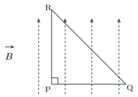
- CBSE 2020Set 55/3/11 markMCQQ.An isosceles right angled current carrying loop PQR is placed in a uniform magnetic field B pointing along PR. If the magnetic force acting on the arm PQ is F, then the magnetic force which acts on the arm QR will be (A) F (B) 2F (C) 2F (D) −F
›Reveal solutionSolution
Figure — CBSE 2020 55/3/1 Q10 The magnetic force on a current-carrying wire in a uniform field depends only on the vector from start to end of the wire, not its shape. For the isosceles right triangle, the force on QR equals the negative of the force on PQ, so the answer is −F.
The key insight here is a beautiful simplification: in a uniform magnetic field, the net magnetic force on any current-carrying wire segment depends only on the vector displacement between its endpoints, not on the path the wire takes between them. This is because the force on a small element dl is Idl×B, and when B is constant, the integral ∫dl over the wire is just the straight-line vector from start to end.
Let's apply this to the triangular loop.
-
Set up the geometry. The loop PQR is an isosceles right triangle with the right angle at P. So PR and PQ are the perpendicular legs, and QR is the hypotenuse. The uniform magnetic field B points along PR. Let's assign directions: take PR along the +y axis, and PQ along the +x axis. Then the current direction matters — we need to be consistent. The loop is closed, so current flows P → Q → R → P (or the reverse; the magnitude of force is unaffected by sign, but direction matters for comparing forces).
-
Force on arm PQ. Arm PQ is a straight wire of length L (say) along the x-axis. The current in PQ flows from P to Q, so dl is along +x^. The magnetic field is B=By^. The force on a straight wire is FPQ=I(LPQ×B), where LPQ is the vector from P to Q (length L, direction +x^).
Compute: LPQ×B=(Lx^)×(By^)=LB(x^×y^)=LBz^.
So FPQ=ILBz^. The magnitude is F=ILB, and it points out of the plane (say upward). The problem states this force is F, so F=ILB.
-
Force on arm QR. Arm QR is the hypotenuse. Its vector from Q to R: Q is at (L,0), R is at (0,L) (since PR = PQ = L for an isosceles right triangle). So LQR=R−Q=(0−L)x^+(L−0)y^=−Lx^+Ly^.
The force: FQR=I(LQR×B)=I[(−Lx^+Ly^)×(By^)].
Compute the cross product term by term:
- (−Lx^)×(By^)=−LB(x^×y^)=−LBz^.
- (Ly^)×(By^)=LB(y^×y^)=0. So FQR=−ILBz^=−Fz^. …
-
- CBSE 2019Set ANNUAL1 markQ.Write formula for force on a current carrying conductor in a magnetic field.
›Reveal solutionSolution
A conductor of length L carrying current I in a magnetic field B feels a force F = I(L x B), of magnitude BIL sin(theta).
Each charge carrier drifting in the wire experiences a magnetic force. Summing over all carriers in a length L gives the force on the whole conductor:
F = I (L x B)
where L points along the direction of conventional current and has magnitude equal to the length of the conductor.
Magnitude: F = B I L sin(theta), theta = angle between L and B. …
🎓Unlock everything free for 14 days
- ✓Full step-by-step solutions
- ✓Concept-first explanations
- ✓Methods, shortcuts & mistakes
- ✓PYQ mapping + timed mock tests
Full access for 14 days. No credit card required.