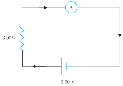
Q.In the circuit (Fig. 4.23) the current is to be measured. What is the value of the current if the ammeter shown
You're viewing a preview — the full solution, concept, methods & PYQ mapping are locked.
Start your 14-day free trial to unlock the full solution →The ammeter's own resistance changes the total circuit resistance, altering the current from its true value. For the galvanometer alone (60 Ω) the current is 0.0476 A; with a 0.02 Ω shunt it becomes 0.993 A; an ideal ammeter (0 Ω) gives exactly 1.00 A.
The core idea here is the ammeter loading effect. An ammeter must be placed in series with the component whose current you want to measure. That means the ammeter's own resistance adds directly to the circuit's total resistance. If the ammeter's resistance is not negligible compared to the rest of the circuit, it reduces the current below what it would be in the undisturbed circuit. The "true" current — the one we actually want to measure — is the current that flows when the ammeter has zero resistance (an ideal ammeter).
The circuit is a simple single-loop: a 3.00 V battery connected in series with a 3.00 Ω resistor and the ammeter. The ammeter's resistance changes in each part of the question.
- Find the true (ideal) current first. This gives us a reference point. With an ideal ammeter (), the total resistance is just the 3.00 Ω resistor.
This is the current that would flow if the ammeter didn't interfere at all.
- Part (a): Galvanometer alone. A galvanometer is a sensitive current detector, but it has a significant internal resistance — here . When placed directly in the circuit as an ammeter, the total resistance becomes:
The current is then:
This is drastically smaller than 1 A. The galvanometer's high resistance has "loaded" the circuit, giving a completely misleading reading. This is why you never use a bare galvanometer as an ammeter for anything but tiny currents.
A common mistake is to forget that the ammeter's resistance is in series with the rest of the circuit. Here, the 60 Ω galvanometer dominates the 3 Ω resistor, so the measured current is only about 5% of the true value.
-
Part (b): Galvanometer with a shunt.
To convert a galvanometer into a useful ammeter, we connect a very small resistance in parallel with the galvanometer coil. This shunt provides an alternative path for most of the current, protecting the delicate galvanometer and drastically reducing the overall resistance of the ammeter.
The ammeter's effective resistance is the parallel combination of and : …
Unlock everything free for 14 days
- Full step-by-step solutions
- Concept-first explanations
- Methods, shortcuts & mistakes
- PYQ mapping + timed mock tests
Full access for 14 days. No credit card required.