Q.An alternating e.m.f. is applied across an inductor. Obtain an expression for the current (I) in the circuit and hence obtain inductive reactance of the circuit and draw a phasor diagram to show phase difference between I and V. OR
🔒You're viewing a preview — the full solution, concept, methods & PYQ mapping are locked.
🔒 Start your 14-day free trial to unlock the full solution →Concept understanding — AC Through an Inductor
AC Through an Inductor: From Intuition to the 90° Lag
The Core Intuition — Why an Inductor "Fights" Change
Imagine you are pushing a heavy box across a floor. If you push steadily, the box moves at a constant speed. But if you try to suddenly jerk it forward, the box resists — its inertia makes it want to stay where it is. The harder you push, the more it pushes back, but only while you are changing the speed.
An inductor does the same thing, but with electric current. It does not resist steady current (DC) — a perfect inductor has zero resistance. What it resists is change in current. The faster you try to change the current, the harder the inductor pushes back with a voltage that opposes that change.
This opposition is called self-induction, and the property that causes it is inductance L, measured in henries (H).
The Physics: Faraday's Law in Action
When current flows through a coil, it creates a magnetic field. If the current changes, the magnetic field changes, and that changing field induces a voltage in the same coil — a back emf. Faraday's law gives the magnitude:
vL=Ldtdi
The sign matters: the induced voltage always acts to oppose the change that produced it (Lenz's law). So if current is increasing (di/dt>0), the inductor generates a voltage that tries to push current the other way — like a spring that pushes back harder the faster you compress it.
A common mistake is to think the inductor "resists" current like a resistor. It does not. It resists change in current. For steady DC, di/dt=0, so vL=0 — the inductor acts like a short circuit.
AC Through an Inductor: The Mathematics
Now feed the inductor with an AC voltage source:
v(t)=Vmsin(ωt)
where ω=2πf is the angular frequency. The circuit equation (Kirchhoff's voltage law) gives:
v(t)=Ldtdi
So:
dtdi=LVmsin(ωt)
Integrate to find the current:
i(t)=∫LVmsin(ωt)dt=−ωLVmcos(ωt)+C
The constant C is zero for steady-state AC (no DC offset). Using cos(ωt)=sin(ωt+90∘):
i(t)=ωLVmsin(ωt−90∘)
i(t)=Imsin(ωt−90∘)whereIm=ωLVm
The 90° Lag — What It Means Physically
Compare the voltage and current:
- Voltage: v(t)=Vmsin(ωt)
- Current: i(t)=Imsin(ωt−90∘)
The current reaches its peak exactly one-quarter cycle after the voltage does. We say current lags voltage by 90° (or π/2 radians).
Why? Look at the derivative relationship. When voltage is at its peak, di/dt is maximum — the current is changing fastest. But the current itself is passing through zero at that instant (think of a sine wave: its steepest slope is at the zero crossing). When voltage passes through zero, di/dt=0, and the current is at its peak (the sine wave is flat at the top).
Visualise it: voltage drives the rate of change of current, not the current itself. So the current waveform is the integral of the voltage waveform — and integrating a sine gives a negative cosine, which is a sine shifted by -90°.
Inductive Reactance — The "AC Resistance"
The amplitude of the current is:
Im=ωLVm
Define inductive reactance XL:
XL=ωL=2πfL
Then Im=Vm/XL, which looks like Ohm's law — but XL is not a resistance. It depends on frequency: …
Applying Kirchhoff's voltage law to a pure inductor (the applied voltage always equals the self-induced back-emf, v=LdI/dt) and integrating gives the current as a function of time, from which both the reactance and the phase relationship follow. …
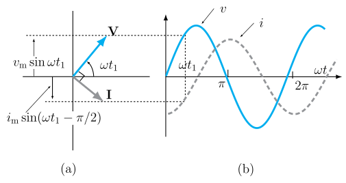
Applying Kirchhoff's voltage law to a pure inductor in an AC circuit and integrating gives a current that lags the voltage by 90°, with peak value I0=V0/ωL.
Setup: Let an inductor of inductance L be connected to an AC source of emf v=V0sinωt. Since the inductor has negligible resistance, at every instant the applied voltage equals the self-induced back-emf:
v=LdtdI
V0sinωt=LdtdI
dI=LV0sinωtdt
Integrating both sides:
I=LV0∫sinωtdt=−ωLV0cosωt+constant
The integration constant (any time-independent, i.e. DC, part of current) has no physical role in a purely AC circuit and is taken as zero. Using −cosωt=sin(ωt−π/2):
I=ωLV0sin(ωt−2π)=I0sin(ωt−2π)
where I0=ωLV0 is the peak current.
Inductive reactance: Comparing I0=V0/(ωL) with the resistive form I0=V0/R, the quantity ωL plays the role of an effective 'resistance' for AC in an inductor, called the inductive reactance:
XL=ωL=2πνL
Its SI unit is ohm (Ω). It increases with frequency — an inductor opposes fast-changing currents more strongly.
…
Showing the 12 most recent of 15 on this concept.
- CBSE 2026Set A1 markMCQQ.Choke coil works on the principle of (A) self induction (B) transient current (C) mutual induction (D) wattless current
›Reveal solutionSolution
A choke coil works on self-induction: its inductance opposes changes in AC current, limiting the current with negligible power loss.
A choke coil is an inductor of large inductance L and small resistance. In an AC circuit it presents an inductive reactance XL=ωL, which arises from the back-emf produced by the coil's own changing flux — i.e. self-induction. This reactance limits the current. Because an ideal inductor's current lags the voltage by 90∘, the average power …
- CBSE 2026Set ANNUAL1 markMCQQ.In an a.c. circuit having pure inductor, current(a) leads the voltage by an angle of π/2(b) leads the voltage by an angle of π(c) lags the voltage by an angle of π/2(d) lags the voltage by an angle of π
›Reveal solutionSolution
In a pure inductor, the back-emf opposes the change in current, forcing the current to lag 90° behind the applied voltage.
For a pure inductor with applied voltage v=v0sin(ωt), the induced back-emf balances the applied voltage: v=Ldtdi. Solving,
i=ωLv0∫sin(ωt)dt=−ωLv0cos(ωt)=ωLv0sin(ωt−2π)
…
- CBSE 2025Set 55/6/11 markMCQQ.An ac source is connected to a resistor and an inductor in series. The voltage across the resistor and inductor are 8 V and 6 V respectively. The voltage of the source is: (A) 10 V (B) 12 V (C) 14 V (D) 16 V
›Reveal solutionSolution
In a series RL circuit, the resistor and inductor voltages are 90° out of phase, so the source voltage is the phasor sum (Pythagorean sum) of the two: 82+62=10 V. The correct option is (A).
Concept and Intuition
When an AC source drives a resistor and an inductor in series, the two components respond differently to the alternating current. The resistor’s voltage is in phase with the current — it rises and falls exactly when the current does. The inductor’s voltage, however, leads the current by 90° (a quarter-cycle ahead). This phase difference means you cannot simply add the two voltages as ordinary numbers (8 V + 6 V = 14 V). That would be a common mistake — it ignores the fact that the peaks of these voltages occur at different times.
Instead, we treat them as phasors — rotating arrows whose lengths represent the voltage magnitudes and whose angles represent the phase. The resistor voltage points along the reference direction (say, the x-axis), and the inductor voltage points 90° ahead (the y-axis). The source voltage is the vector sum of these two perpendicular phasors. That’s why the Pythagorean theorem gives the answer.
Watch outNever add RMS voltages of different components in an AC circuit as if they were DC voltages. The phase difference (here 90° for a pure inductor) makes the total less than the arithmetic sum. 8 + 6 = 14 V is a trap — the correct answer is 10 V.
Step-by-Step Solution
-
Identify the given data.
Voltage across resistor: VR=8 V (RMS value).
Voltage across inductor: VL=6 V (RMS value).
The circuit is a series RL combination connected to an AC source.
-
Recall the phase relationship.
In a series RL circuit, the current I is the same through both components.
- For the resistor: VR=IR, and VR is in phase with I.
- For the inductor: VL=IXL, and VL leads I by 90∘. …
-
- CBSE 2025Set D1 markMCQQ.In a purely inductive circuit, the power factor is (A) 0 (B) 1 (C) 0.5 (D) infinity
›Reveal solutionSolution
In a pure inductor current lags voltage by 90°, so power factor cos φ = cos 90° = 0 (no average power consumed).
In a purely inductive a.c. circuit, the current lags the applied voltage by a phase angle of 90° (φ = 90°).
The power factor is
cosϕ=cos90∘=0
…
- CBSE 2025Set ANNUAL1 markQ.In a purely inductive a.c. circuit the alternating current lags behind the alternating voltage by ____________ phase angle.
›Reveal solutionSolution
In a purely inductive circuit, the back-EMF from the inductor makes the current reach its peak a quarter-cycle after the voltage — a 90 degree phase lag.
For a purely inductive AC circuit with applied voltage V=V0sinωt, the current is:
I=ωLV0sin(ωt−2π)
…
- CBSE 2023Set B1 markQ.Fill in the blank: The ohmic resistance of an ideal inductance is ______.
›Reveal solutionSolution
An ideal inductor is made of resistance-less wire, so its DC/ohmic resistance is zero; it opposes AC only through inductive reactance XL=ωL.
An 'ideal inductance' is an idealised coil that has inductance but is assumed to be wound from a perfect (zero-resistance) conductor. It therefore has zero ohmic resistance — it does not dissipate energy as heat (I2R loss = 0). Its opposition to alternating current comes entirely from the induced back-emf, characterised by the inductive reactance XL=ωL=2πfL, not from resistance. In …
- CBSE 2023Set ANNUAL1 markQ.What is inductive reactance? Write its SI unit.
›Reveal solutionSolution
Inductive reactance XL=ωL measures how strongly a pure inductor opposes AC flow; unlike resistance it depends on frequency and vanishes for DC.
When a pure inductor of self-inductance L carries an alternating current i=i0sinωt, it develops a self-induced back emf e=−Ldtdi that opposes the applied voltage. For the source voltage v=v0sinωt to drive this current, the peak values are related by
v0=i0ωL
Comparing this with Ohm's law form v0=i0R, the quantity ωL plays the role of an 'AC resistance' for the inductor and is called inductive reactance:
XL=ωL=2πfL
where f is the frequency of the AC supply and L is in henry (H).
…
- CBSE 2022Set I1 markMCQQ.Inductive reactance is (A) X_L = 2πfL (B) X_L = 2πf^2 L (C) X_L = 2πfL^2 (D) X_L = 2πf^2 L^2
›Reveal solutionSolution
Inductive reactance XL=ωL=2πfL.
For an inductor of inductance L in an AC circuit of frequency f (angular frequency ω=2πf), the opposition it offers to the alternating current is the inductive reactance:
XL=ωL=2πfL.
…
- CBSE 2022Set TERM21 markMCQQ.Dimensional formula for inductive reactance is:(a) ML²T⁻²A⁻³(b) ML²T⁻²A⁻²(c) ML²T⁻³A⁻²(d) ML⁻²T⁻²A⁻¹
›Reveal solutionSolution
Inductive reactance XL=ωL has the same units as resistance (Ohm), since V=IXL.
Inductive reactance is defined by XL=ωL, and it appears in V=IXL (Ohm's-law-like relation for an inductor), so it must carry the same dimensions as resistance R=V/I.
Voltage: [V]=[ML2T−3A−1] …
- CBSE 2021Set A1 markMCQQ.Inductive reactance offered by an inductor of inductance L in ac circuit of angular frequency ω is (A) ω/L (B) ω . L (C) 1/ω.L (D) L/ω
›Reveal solutionSolution
Inductive reactance X_L = ωL.
An inductor opposes changes in current in an ac circuit. This opposition, called inductive reactance, is:
XL=ωL=2πfL
…
- CBSE 2020Set HE8211 markQ.Fill in the blank: S.I. unit of inductive reactance (Xₗ) is ______.
›Reveal solutionSolution
Inductive reactance has the same unit as resistance: ohm.
Inductive reactance is defined as XL=ωL=2πfL, where L is inductance (henry) and ω/f is angular/linear frequency. Since XL=V/I (from Ohm's-law-like be …
- CBSE 2020Set ANNUAL1 markQ.In a purely inductive AC circuit, the current leads the e.m.f. by phase π/2. (Write 'True' or 'False'.)
›Reveal solutionSolution
The statement is False: in a purely inductive circuit, current lags voltage by π/2 (not leads).
For a purely inductive AC circuit with e.m.f. ε=ε0sinωt, the induced back e.m.f. across the inductor must balance the applied e.m.f., giving:
Ldtdi=ε0sinωt
Integrating:
i=ωLε0(−cosωt)=ωLε0sin(ωt−2π)
…
🎓Unlock everything free for 14 days
- ✓Full step-by-step solutions
- ✓Concept-first explanations
- ✓Methods, shortcuts & mistakes
- ✓PYQ mapping + timed mock tests
Full access for 14 days. No credit card required.