Question of 50
Q.Using phasor diagram, derive an expression for the impedance of a series LCR-circuit. What do you mean by the resonance condition of a series LCR-circuit? Calculate its resonant frequency. OR A series LCR circuit connected to a variable frequency 230 V source. L = 5.0 H, C = 80 μF, R = 40 Ω.
(a) Determine the source frequency which drives the circuit in resonance.
(b) Obtain the impedance of the circuit and the amplitude of current at the resonating frequency.
(c) Determine the rms potential drops across the three elements of the circuit. Show that the potential drop across the LC combination is zero at the resonating frequency.
Himachal HpboseHPBOSE Plus Two Board 2026Subjective· 5mImportance★★★★★
0% · 0/50 Questions
You're viewing a preview — the full solution, concept, methods & PYQ mapping are locked.
Start your 14-day free trial to unlock the full solution →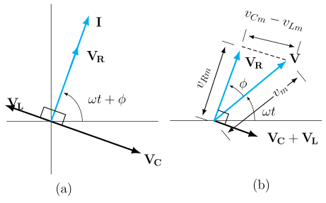
Adding the phasors for , , gives ; at resonance the reactances cancel, current is maximum, and .
Setting up the phasor diagram: In a series LCR circuit driven by , the same current flows through all three elements. Represent the current phasor along a reference axis. Then:
- Voltage across R, , is IN PHASE with the current (along the same axis).
- Voltage across L, (where ), LEADS the current by (drawn perpendicular, rotated ).
- Voltage across C, (where ), LAGS the current by (drawn perpendicular, rotated , i.e. opposite to ).
Since and are exactly opposite (180° apart) on the phasor diagram, they combine to a single net phasor of magnitude , perpendicular to .
Resultant voltage (vector sum of and , which are mutually perpendicular):
Defining impedance :
…
Unlock everything free for 14 days
- Full step-by-step solutions
- Concept-first explanations
- Methods, shortcuts & mistakes
- PYQ mapping + timed mock tests
Full access for 14 days. No credit card required.