Q.(a) Derive an expression for impedance in a series LCR circuit and hence arrive at an expression for resonant frequency of the circuit.
You're viewing a preview — the full solution, concept, methods & PYQ mapping are locked.
Start your 14-day free trial to unlock the full solution →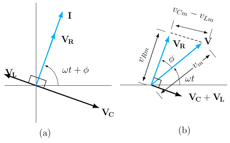
Impedance of a series LCR circuit is ; it is minimum, and the current maximum, when , defining the resonant angular frequency . For the given L and C, this works out to about 35.3 Hz — quite different from the 50 Hz source frequency, showing resonance depends only on L and C, not on the actual driving frequency.
(a) Impedance and resonant frequency: In a series LCR circuit driven by , the same current flows through all three elements. Using phasors: the voltage across R is in phase with current (phasor length ); across L it leads current by 90° (phasor length , ); across C it lags current by 90° (phasor length , ). Since and are exactly opposite (180° apart) as phasors, they partially cancel, leaving a net reactive phasor of perpendicular to the resistive phasor . Adding these perpendicular phasors (Pythagoras):
As the driving frequency ω is varied, Z is minimum (equal to just R, and current is maximum) when the reactive part vanishes:
This is the condition of resonance — the circuit's natural (LC) oscillation frequency, at which the current amplitude is largest for a given driving voltage amplitude.
…
Unlock everything free for 14 days
- Full step-by-step solutions
- Concept-first explanations
- Methods, shortcuts & mistakes
- PYQ mapping + timed mock tests
Full access for 14 days. No credit card required.