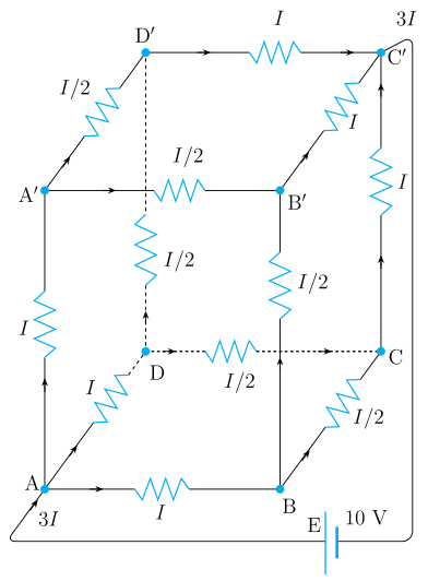
Q.A battery of 10 V and negligible internal resistance is connected across the diagonally opposite corners of a cubical network consisting of 12 resistors each of resistance 1 Ω (Fig. 3.16). Determine the equivalent resistance of the network and the current along each edge of the cube.
Concept understanding — Wheatstone Bridge Symmetry
Wheatstone Bridge Symmetry
Four resistors are arranged in a diamond. A battery sits across the top and bottom points; a sensitive galvanometer bridges the left and right points. The question is: when does no current flow through the galvanometer? The answer is symmetry.
The Intuition
Treat the bridge as two parallel voltage dividers — two resistors in series on the left, two in series on the right — with the galvanometer joining their midpoints. If both dividers produce the same midpoint voltage, there is no potential difference across the galvanometer and no current flows: the bridge is balanced. This happens when the resistance ratio on the left arm equals the ratio on the right arm.
Symmetry here means equal ratios, not equal resistances. 1 Ω with 2 Ω on one side balances 100 Ω with 200 Ω on the other.
The Precise Statement
Label the four resistors: R1 top-left, R2 bottom-left, R3 top-right, R4 bottom-right. The battery connects the top junction (between R1, R3) to the bottom junction (between R2, R4); the galvanometer connects the two midpoints. The bridge is balanced when
R2R1=R4R3
The balance condition is independent of the battery voltage and of the galvanometer's resistance — it depends only on the four resistor values.
Why This Matters
- Unknown resistance: put the unknown in place of R4, adjust the others until balanced, then R4=R3R1R2.
- Strain gauges: stretching slightly changes a resistance, unbalancing the bridge; the deflection measures the strain.
- Temperature sensors: a temperature-dependent resistor unbalances the bridge in proportion to the change.
Do not memorise "opposite resistors are equal." That is only the special case where both ratios equal 1. Memorise the ratio condition R2R1=R4R3.
Quick Check
If R1=4 Ω, R2=6 Ω, R3=2 Ω, find R4 for balance:
64=R42⇒R4=3 Ω
No two resistors are equal, yet the ratios match — so the bridge balances. That proportionality of the two voltage dividers is the whole idea of Wheatstone-bridge symmetry.
The Wheatstone bridge balance condition is a well-established part of the NCERT Class 12 Physics chapter on current electricity, and "Wheatstone bridge balance condition derivation class 12 physics" is a frequently asked CBSE board and JEE Main question. This ratio-based reasoning, rather than assuming equal resistors, is exactly what NCERT-aligned answer keys expect.
Why this formula?
Wheatstone Bridge Symmetry — Why the Formula Holds
The Wheatstone bridge is a circuit used to measure an unknown resistance by balancing two legs of a bridge. The key result is:
When the bridge is balanced, no current flows through the galvanometer, and:
R2R1=R4R3
Let's understand why this is true — not just memorize it.
1. The Circuit Setup
A Wheatstone bridge has four resistors arranged in a diamond:
- R1 and R2 in series on the left branch
- R3 and R4 in series on the right branch
- A galvanometer (sensitive current detector) connects the midpoints of the two branches
- A battery connects across the top and bottom
        A
       / \
      /   \
     R1    R3
     |     |
     G-----|   (G = galvanometer)
     |     |
     R2    R4
      \   /
       \ /
        B
2. The Condition for Balance — "No Current Through G"
Balance means the galvanometer shows zero deflection — no current flows through it. This implies points C (between R1 and R2) and D (between R3 and R4) are at the same electric potential. If VC=VD, no potential difference exists across the galvanometer, so no current flows.
3. Deriving the Ratio — Step by Step
Step 1: Branch currents
With no current through G, the left branch carries a single current I1 and the right branch a single current I2.
Step 2: Equal potentials at the midpoints
From A (common top) to the midpoints, since VC=VD:
I1R1=I2R3(1)
From the midpoints to B (common bottom), since VC=VD:
I1R2=I2R4(2)
Step 3: Divide (1) by (2)
I1R2I1R1=I2R4I2R3
The currents I1 and I2 cancel:
R2R1=R4R3
4. Why This Makes Physical Sense
The bridge is essentially two voltage dividers sharing the same input voltage. Balance occurs when both dividers produce the same output voltage at their midpoints. Notice that I1 and I2 need not be equal — the balance condition fixes only the ratio of resistances in each branch, not their individual values.
5. Key Exam Takeaways
| Concept | Why it matters |
|---|---|
| No current through G | Implies VC=VD |
| Voltage division | Each branch acts as an independent divider |
| Ratio equality | Direct consequence of equal potentials |
Balance = equal potentials → equal voltage ratios → R2R1=R4R3
The network is symmetric about the body diagonal from the entry corner A to the opposite corner G, and all 12 edges are 1 Ω.
Symmetry currents. Let the total current be I. It splits equally among the three edges at A (current I/3 each). Each of these reaches a vertex where it divides into two of the six middle edges (I/6 each). At the far end three middle edges feed each of the three edges into G (I/3 each).
Equivalent resistance. Add the potential drops along a path A→(adjacent)→(middle)→G:
V=3I(1)+6I(1)+3I(1)=I(31+61+31)=65I.
With V=10 V: 65I=10⇒I=12 A, so
Req=IV=1210=65 Ω.
Edge currents. I/3=4 A on each of the three edges at A and the three at G; I/6=2 A on each of the six middle edges.
Equivalent resistance Req=65 Ω≈0.83 Ω; total current 12 A. Each of the six edges touching the entry and exit corners carries 4 A, and each of the six middle edges carries 2 A.
Using the three-fold symmetry of a cube fed across its body diagonal, the twelve 1 Ω edges reduce to Req=65 Ω; the 10 V cell drives 12 A, giving 4 A in each of the six edges at the two corners and 2 A in each of the six middle edges.
Setting up the symmetry. The battery is across the body diagonal, from corner A (entry) to the opposite corner G (exit). Three edges leave A; by symmetry they are indistinguishable, so the total current I splits equally: I/3 in each. Each such edge ends on a vertex adjacent to A; from there two edges continue toward G, so by symmetry the I/3 splits into I/6 in each of these six 'middle' edges. Finally three edges arrive at G, each carrying I/3 (pairs of middle edges of I/6 merging).
Potential drop along a diagonal path. Follow A→B→F→G (adjacent → middle → exit):
VA−VG=3I×1+6I×1+3I×1=I(31+61+31)=65I.
Equivalent resistance. This drop equals the battery voltage, 65I=10 V, and by definition V=IReq, so
Req=65 Ω≈0.83 Ω.
Total and branch currents.
I=ReqV=5/610=12 A.
- Three edges at A and three at G: I/3=4 A each.
- Six middle edges: I/6=2 A each.
Req=65 Ω≈0.83 Ω; total current =12 A. Current =4 A in each of the six edges meeting the entry and exit corners, and 2 A in each of the six middle edges.
Method: Exploiting Symmetry to Reduce Resistor Networks
This method solves resistor networks with multiple identical branches (e.g. a cube, wire mesh, or ladder network) fed between two symmetric terminals, without writing individual Kirchhoff equations for every branch.
Steps
Step 1: Identify equivalent points via symmetry
Look at the geometry of the network relative to the entry and exit terminals. If several branches are indistinguishable from the source's point of view (same distance, same connectivity, mirror images of one another), by symmetry they must carry equal currents and their far ends must sit at equal potentials.
Step 2: Group vertices into equipotential "shells"
Points that are equidistant from the entry terminal along equivalent paths are at the same potential. This lets you assign a single current variable to each symmetric group of edges, rather than one variable per edge.
Step 3: Distribute the total current using symmetry counts
If n identical edges leave a junction and, by symmetry, must carry equal current, each carries I/n of whatever current arrives there. Track how the current I from the source splits and recombines through each successive shell of the network.
Step 4: Sum potential drops along ONE representative path
Every direct path from the entry to the exit terminal must produce the same total potential drop V (the applied voltage). Pick the simplest such path and add up the IR drop across each segment along it:
V=∑iIiRi(along one representative path, entry to exit)
Solve this single equation for the overall current I.
Step 5: Applying to this problem
Once I is known, Req=V/I, and the current in any individual edge follows directly from the symmetry grouping set up in Step 2 — e.g. edges nearest the entry/exit terminals carry a larger fractional share of I than the "equatorial" edges further from either terminal.
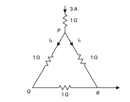
- COMEDK 2026Set 2026-M1 markMCQQ.A current of 3 A enters one vertex P of an equilateral triangle PQR having three resistors of 1Ω each forming the sides of the equilateral triangle as shown. The value of i2 in amperes is: (A) 2 A (B) 1.7 A (C) 1 A (D) 1.5 A
›Reveal solutionSolution
The circuit is a symmetric delta network; using Kirchhoff’s laws and symmetry, the current i2 through side PQ is found to be 1 A. The correct option is (C).
The key insight is that the three resistors are identical and form a closed loop (a delta network). The 3 A current enters at vertex P and leaves at vertex R. Because the resistors are all 1Ω, the network is symmetric with respect to the line through P and the midpoint of QR — but here the exit is at R, not at the midpoint, so we cannot simply split the current equally. Instead, we must apply Kirchhoff’s current law (KCL) at the junctions and Kirchhoff’s voltage law (KVL) around the loop.
Let’s label the currents clearly:
- i1 flows from P to R (right side).
- i2 flows from P to Q (left side).
- Let i3 be the current from Q to R along the bottom side.
At vertex P, the incoming 3 A splits into i1 and i2:
i1+i2=3(1)
At vertex Q, current i2 arrives from P, and then leaves via the bottom resistor toward R. So at Q:
i2=i3(2)
At vertex R, current i1 arrives from P, and current i3 arrives from Q; both leave the network as the outgoing current (which must be 3 A, since current is conserved). So:
i1+i3=3(3)
Now apply Kirchhoff’s voltage law around the triangle P→Q→R→P. Going clockwise:
- From P to Q: voltage drop = i2×1Ω=i2 (positive if we go with the current direction).
- From Q to R: voltage drop = i3×1Ω=i3 (direction from Q to R matches our assumed current).
- From R back to P: voltage drop = −i1×1Ω=−i1 (because we are going opposite to the direction of i1).
Sum of voltage drops around the closed loop must be zero:
i2+i3−i1=0(4)
Now we have four equations, but only three unknowns. Solve them:
From (2): i3=i2.
Substitute into (1) and (3):
- (1): i1+i2=3
- (3): i1+i2=3 (same equation, so it’s consistent). Now (4): i2+i2−i1=0⇒2i2−i1=0⇒i1=2i2.
Plug into (1): 2i2+i2=3⇒3i2=3⇒i2=1 A.
Thus the current through the left side PQ is 1 ampere.
Watch outA common mistake is to assume the current splits equally because the resistors are equal. But the exit point is at R, not at the midpoint of QR, so the symmetry is broken — the path P→R has only one resistor, while P→Q→R has two resistors, so less current flows through the longer path.
TipNotice that the bottom resistor carries the same current as the left side (i3=i2). This is because at Q, the only way out is through the bottom resistor — no other branch. So the left side and bottom side form a series path from P to R, while the right side is a direct parallel path. The voltage across both paths must be equal, giving i1=2i2.
✓Final answerThe correct option is (C).
ANSWER: C
- KCET 2026Set C21 markMCQQ.In the figure
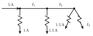 , the values of currents I1, I2 and I3 respectively are
(A) 6A, 1.5A and 1A
(B) 4A, 2.5A and 2A
(C) 4A, 2.5A and 1A
(D) 6A, 4.5A and 1.5A
, the values of currents I1, I2 and I3 respectively are
(A) 6A, 1.5A and 1A
(B) 4A, 2.5A and 2A
(C) 4A, 2.5A and 1A
(D) 6A, 4.5A and 1.5A›Reveal solutionSolution
Kirchhoff's Current Law (junction rule) applied successively at each of the 3 branch points gives I1, I2, and I3 directly from the branch currents printed in the figure.
Step 1 — First junction
The figure shows 5A entering the first junction, with 1A branching off downward. By KCL, the current continuing along the main line is
I1=5A−1A=4A
Step 2 — Second junction
At the second junction, the figure shows 1.5A branching off downward from the I1=4A arriving there. By KCL, the current continuing along the main line is
I2=4A−1.5A=2.5A
Step 3 — Third junction
At the final junction, the I2=2.5A arriving splits into two branches, one of which the figure marks as 1.5A. By KCL, the other branch is
I3=2.5A−1.5A=1A
At every junction, the current entering equals the sum of the currents leaving, so the full 5A supplied at the input is accounted for across the whole network.
✓Final answerThe correct option is (C) — I1=4A, I2=2.5A and I3=1A.
- KCET 2025Set D-41 markMCQQ.Two cells of emfs E1 and E2 and internal resistances r1 and r2 (E2>E1 and r2>r1) respectively, are connected in parallel as shown in figure. The equivalent emf of the combination is Eeq. Then (A) E1<Eeq<E2 and Eeq is nearer E2 (B) Eeq>E2 (C) Eeq<E1 (D) E1<Eeq<E2 and Eeq is nearer E1
›Reveal solutionSolution
Eeq is the weighted mean (E1r2+E2r1)/(r1+r2), so it lies between the two emfs and is pulled towards the emf whose cell has the smaller internal resistance — here E1.
Step 1 — Derive the equivalent emf.
For two cells in parallel, the total current is the sum of branch currents. With terminal voltage V:
I=I1+I2=r1E1−V+r2E2−V
Rearranging into the form V=Eeq−Ireq gives the standard results
Eeq=r1+r2E1r2+E2r1,req=r1+r2r1r2
Step 2 — Note that it is a weighted average.
Write it as
Eeq=w1r1+r2r2E1+w2r1+r2r1E2,w1+w2=1, w1,w2>0
A convex combination of E1 and E2 must lie strictly between them, so with E2>E1:
E1<Eeq<E2
This already eliminates (B) and (C).
Step 3 — Decide which emf it is nearer.
Crucially, E1 carries the weight w1=r2/(r1+r2) — the other cell's resistance. Given r2>r1:
w1=r1+r2r2>21>r1+r2r1=w2
The dominant weight sits on E1, so Eeq is nearer to E1.
Sanity check with numbers: E1=2V, E2=4V, r1=1Ω, r2=3Ω:
Eeq=1+32(3)+4(1)=410=2.5 V
which indeed lies between 2 V and 4 V, and is much closer to E1=2 V. ✓
✓Final answerThe correct option is (D) — E1<Eeq<E2 and Eeq is nearer E1.
ANSWER: D
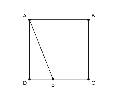
- COMEDK 2024Set 2024-A1 markMCQQ.A wire of uniform cross section and resistance 4 ohms is bent in the shape of square ABCD. Point A is connected to a point P on DC by a wire AP of resistance 1ohm. When a potential difference is applied between A and C, the points B and P are seen to be in same potential. What is the resistance of part DP ? (A) 2−1 Ohm (B) 2 Ohm (C) 1 Ohm (D) Zero Ohm
›Reveal solutionSolution
Imposing VB=VP gives x2+2x−1=0, so the resistance of DP is 2−1 Ω.
The square ABCD (total wire 4Ω) has each side 1Ω: AB=BC=CD=DA=1Ω. Wire AP=1Ω joins A to P on DC. Let DP=x, PC=1−x. Apply p.d. between A and C; take VA=V, VC=0.
Potential of B (branch A–B–C, series 2Ω): VB=2V.
Impose VP=2V and use node equations at D and P.
At D: 1VD−V+xVD−VP=0⇒VD=x+1V(x+21).
At P: xVP−VD+1−xVP+1VP−V=0. Substituting (with V/2−VD=−2(x+1)Vx):
−x+11+1−x1−1=0⇒1−x1−1+x1=1.
Hence 1−x22x=1⇒x2+2x−1=0⇒x=2−1 Ω.
✓Final answerThe correct option is (A) — (2−1) Ohm
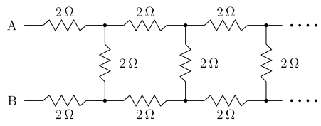
- KCET 2023Set A-31 markMCQQ.The equivalent resistance between the points A and B in the following circuit is
 (A) 5.5 Ω
(B) 0.05 Ω
(C) 5 Ω
(D) 0.5 Ω
(A) 5.5 Ω
(B) 0.05 Ω
(C) 5 Ω
(D) 0.5 Ω›Reveal solutionSolution
Exploit self-similarity: an infinite ladder looks the same after you strip off its first section, which turns the problem into a quadratic equation for R.
1. The self-similarity trick
Let R be the resistance looking into the ladder at A–B. Strip off the first section: a 2Ω resistor in the top rail, a 2Ω resistor in the bottom rail, and the first 2Ω shunt rung. What lies beyond that rung is again an infinite ladder identical to the original, so its resistance is also R.
Hence the first shunt (2Ω) is in parallel with R, and that combination is in series with the two 2Ω rail resistors:
R=2+2+(2∥R)=4+2+R2R
2. Solve the equation
Multiply through by (2+R):
R(2+R)=4(2+R)+2R
2R+R2=8+4R+2R
R2+2R−6R−8=0
R2−4R−8=0
R=24±16+32=24±48=2±23
3. Choose the physical root
Resistance must be positive, and 2−23≈−1.46Ω is negative, so we discard it:
R=2+23=2+3.46=5.46 Ω≈5.5 Ω
Sanity check: R must exceed the 4Ω of the two series rail resistors alone (the rest of the ladder can only add), and it must be less than 4+2=6Ω (the case where the ladder beyond the first rung were an open circuit... more precisely the shunt alone caps the extra at 2Ω). Indeed 4<5.46<6. ✓
✓Final answerThe correct option is (A) — 5.5 Ω.
ANSWER: A
- KCET 2020Set A-11 markMCQQ.Each resistance in the given cubical network has resistance of 1Ω and equivalent resistance between A and B is:
(A) 65Ω
(B) 56Ω
(C) 125Ω
(D) 512Ω
›Reveal solutionSolution
By exploiting symmetry to identify equipotential points, the cube’s resistor network simplifies to a combination of series and parallel branches. The equivalent resistance between A and B is 65Ω, which corresponds to option (A).
The key to solving a cubical resistor network is symmetry. When current enters at A and leaves at B, the geometry of the cube creates points that are at the same potential. You can then “short” those points (connect them without changing the circuit) and redraw the network into a much simpler one.
Let’s work through it step by step.
-
Identify the symmetry.
The cube has 12 edges, each a 1Ω resistor. Current enters at vertex A and exits at vertex B. Because the cube is symmetric about the line AB, the three vertices that are one edge away from A (call them C, D, E) are all at the same potential. Similarly, the three vertices that are one edge away from B (call them F, G, H) are also at the same potential. The remaining two vertices (the ones diagonally opposite on the faces not containing A or B) are also symmetric.
TipIn a cube, the vertices that are equidistant from the entry and exit points are equipotential. Here, the three neighbours of A are all at one potential, and the three neighbours of B are at another.
-
Redraw the network using equipotential points.
Since the three neighbours of A are at the same potential, you can join them into a single node. Same for the three neighbours of B. This collapses the cube into a simpler circuit:
- From A, three 1Ω resistors go to the “middle” node (the three neighbours of A).
- From that middle node, six resistors go to the other middle node (the three neighbours of B) — but careful: each of the three neighbours of A is connected to two of the neighbours of B via the cube’s edges. That gives 3×2=6 resistors, each 1Ω, all in parallel between the two middle nodes.
- Finally, from the second middle node, three 1Ω resistors go to B.
-
Calculate the equivalent resistance step by step.
- From A to the first middle node: three 1Ω resistors in parallel.
R1=31Ω
- Between the two middle nodes: six 1Ω resistors in parallel.
R2=61Ω
- From the second middle node to B: again three 1Ω resistors in parallel.
R3=31Ω
These three resistances are in series (current must go from A to the first middle node, then across to the second, then to B). So:
Req=R1+R2+R3=31+61+31
Watch outA common mistake is to forget that the six resistors between the two middle nodes are all in parallel — students sometimes treat them as series or miss some edges. Count carefully: each of the three neighbours of A connects to two neighbours of B, giving six distinct paths.
- Simplify the sum.
Req=62+61+62=65Ω
✓Final answerThe equivalent resistance is 65Ω, which is option (A).
-
- KCET 2019Set A-11 markMCQQ.The readings of ammeter and voltmeter in the following circuit are respectively (A) 1.2 A, 120 V (B) 1.5 A, 100 V (C) 2.7 A, 220 V (D) 2.2 A, 220 V
›Reveal solutionSolution
In an AC circuit the meters read RMS values. For this series R-L circuit the ammeter reads the RMS current drawn from the 220 V source and the voltmeter reads 220 V, so the correct option is (D): 2.2 A and 220 V.
In an AC circuit the ammeter and voltmeter measure RMS values. The resistor and inductor are in series across the 220 V, 50 Hz supply. The ammeter gives the total RMS current, and the voltmeter reads 220 V.
1. Inductive reactance.
With L=π0.7 mH and f=50 Hz,
XL=2πfL=2π×50×π0.7×10−3=100×0.7×10−3=0.07 Ω
This is negligible compared with R=100 Ω, so the impedance is essentially resistive: Z≈R=100 Ω.
2. Ammeter reading (RMS current).
I=ZVs≈100220=2.2 A
3. Voltmeter reading.
The voltmeter reads the supply voltage, 220 V.
Thus the readings are 2.2 A and 220 V.
✓Final answerThe correct option is (D): ammeter reads 2.2 A, voltmeter reads 220 V.
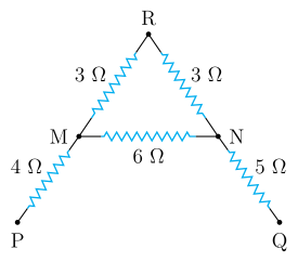
- KCET 2018Set A-11 markMCQQ.The effective resistance between P and Q for the following network is
 (A) 121 Ω
(B) 21 Ω
(C) 12 Ω
(D) 211 Ω
(A) 121 Ω
(B) 21 Ω
(C) 12 Ω
(D) 211 Ω›Reveal solutionSolution
Between nodes M and N there are two parallel routes — the 6 Ω cross-bar and the 3 Ω + 3 Ω path through the apex R — which reduce to 3 Ω; then simply add the 4 Ω and 5 Ω legs in series.
Step 1 — Map the network onto its nodes
From the figure the connections are:
- P→M : 4Ω
- M→R (apex) : 3Ω
- R→N : 3Ω
- M→N (cross-bar) : 6Ω
- N→Q : 5Ω
The key observation: the apex R is a dead-end junction with only two resistors attached, so current entering it from M must all leave to N. The path M→R→N is therefore a plain series chain.
Step 2 — Collapse the series pair through the apex
RMRN=3+3=6Ω
Step 3 — Combine it with the cross-bar (parallel)
The 6 Ω chain M−R−N and the 6 Ω cross-bar M−N have the same two end nodes, M and N — that is precisely the definition of being in parallel:
RMN1=61+61=62=31⟹RMN=3Ω
(For two equal resistors in parallel the result is simply half of one of them: 6/2=3Ω.)
Step 4 — Add the two legs in series
Current entering at P has only one route: P→M (4 Ω), then through the M–N combination (3 Ω), then N→Q (5 Ω). Same current flows through all three in turn ⇒ series ⇒ resistances add:
RPQ=4+RMN+5=4+3+5=12Ω
Step 5 — Sanity-check the distractors
- (B) 21 Ω — what you get if you wrongly add everything in series (4+3+6+3+5), ignoring the parallel loop.
- (A) 1/12 Ω and (D) 1/21 Ω — these are the reciprocals of 12 and 21, i.e. the classic slip of forgetting to invert 1/R at the end of the parallel step. Note also that the answer must be larger than any single resistor here (the 4 Ω and 5 Ω legs alone already give 9 Ω), so any fraction-of-an-ohm answer is impossible on inspection.
✓Final answerThe correct option is (C) — 12 Ω.
ANSWER: C
🎓Unlock everything free for 14 days
- ✓Full step-by-step solutions
- ✓Concept-first explanations
- ✓Methods, shortcuts & mistakes
- ✓PYQ mapping + timed mock tests
Full access for 14 days. No credit card required.