Q.A wheel with 10 metallic spokes each 0.5 m long is rotated with a speed of 120 rev/min in a plane normal to the horizontal component of earth's magnetic field HE at a place. If HE=0.4 G at the place, what is the induced emf between the axle and the rim of the wheel? Note that 1 G=10−4 T.
🔒You're viewing a preview — the full solution, concept, methods & PYQ mapping are locked.
🔒 Start your 14-day free trial to unlock the full solution →Concept understanding — Motional Emf
Motional Emf
When a conductor moves through a magnetic field, the free charges inside it experience a magnetic force. This force pushes the charges along the conductor, setting up a potential difference across its ends — a motional emf. It is electromagnetic induction viewed from a moving conductor rather than from a changing field.
Origin: the Lorentz force
Consider a straight rod of length l moving with velocity v perpendicular to a uniform field B. Each free charge q feels a force
F=q(v×B)
of magnitude qvB directed along the rod. Charges pile up at the ends until the electric field they create balances the magnetic force. The resulting potential difference — the motional emf — is
ε=Bvl
Consistency with Faraday's law
Let the rod of length l slide along parallel conducting rails, sweeping out a distance x. The enclosed area is A=lx, so the flux is Φ=Blx. Then
ε=−dtdΦ=−Bldtdx=−Blv
The magnitude Bvl matches the Lorentz-force result, showing that the flux rule and the force picture agree.
Worked example
A rod of length 0.4m moves at 5m/s perpendicular to a field of 0.5T:
ε=Bvl=0.5×5×0.4=1V
If the circuit resistance is 2Ω, the induced current is I=ε/R=0.5A.
Force and energy …
Why this formula?
Motional EMF: Why the Formula Holds
Let's build this from first principles — understanding the why before the formula.
The Core Idea
Motional EMF arises when a conductor moves through a magnetic field. The key insight: moving charges in a magnetic field experience a magnetic force, which acts like a battery pushing charges around the conductor.
Step 1: The Force on a Moving Charge
A charge q moving with velocity v in a magnetic field B feels the Lorentz magnetic force:
Fm=q(v×B)
This force is perpendicular to both velocity and magnetic field.
Step 2: What Happens Inside a Moving Conductor
Consider a straight metal rod of length L moving with constant velocity v perpendicular to a uniform magnetic field B (pointing into the page).
- Free electrons in the rod are moving with the rod at velocity v.
- Each electron experiences a magnetic force:
Fm=−e(v×B)
(negative sign because electron charge is −e)
- This force pushes electrons along the rod — say, toward one end.
Step 3: Charge Separation Creates an Electric Field
As electrons accumulate at one end, that end becomes negatively charged, leaving the other end positively charged.
- This charge separation creates an internal electric field E inside the rod, pointing from positive to negative end.
- The electric field exerts an opposing force on the electrons:
Fe=−eE
Step 4: Equilibrium — The "Battery" is Formed
Charge keeps moving until the electric force balances the magnetic force:
Fe+Fm=0
−eE−e(v×B)=0
E=−(v×B)
Magnitude-wise (for perpendicular v and B):
E=vB
Step 5: From Electric Field to EMF
The motional EMF E is the work done per unit charge to move a test charge from one end to the other:
E=∫negativepositiveE⋅dl
For a uniform field along the rod of length L:
E=E⋅L=vBL
The Key Formula
Motional EMF for a straight conductor moving perpendicular to B:
E=BLv
Why This Makes Physical Sense
| Quantity | Role |
|---|---|
| B | Stronger magnetic field → larger force on charges |
| L | Longer conductor → more charge separation possible |
Concept: Motional Emf – each spoke acts as a rotating rod cutting magnetic field lines. The induced emf across a spoke is the same as that of a single rod rotating about one end.
Steps:
-
Angular speed:
ω=120 rev/min=120×602π=4π rad/s.
-
Magnetic field in SI:
HE=0.4 G=0.4×10−4=4×10⁻⁵ T.
-
Motional emf for one spoke (length L=0.5 m):
Espoke=21BωL2=21×(4×10−5)×(4π)×(0.5)2.
-
Compute: …
The wheel acts as a set of parallel spokes, each a radial conductor cutting the magnetic field. The induced emf between axle and rim is the same as that from a single spoke, calculated using motional emf for a rotating rod: E=21BωL2. The answer is 6.28×10⁻⁵ V.
The key insight here is that each metallic spoke is like a rod rotating about one end in a uniform magnetic field. The axle and rim act as the two terminals, and all spokes are connected in parallel between them — so the net emf is just the emf of one spoke.
Why motional emf works here
When a conductor moves in a magnetic field, free electrons experience a magnetic force q(v×B), which pushes them along the conductor until an electric field builds up to balance it. The resulting potential difference is the motional emf. For a rod rotating in a uniform field perpendicular to its plane, different parts of the rod move at different speeds — so we integrate the emf contribution along its length.
For a rod of length L rotating with angular speed ω in a uniform magnetic field B perpendicular to its plane, the induced emf between the centre and the rim is:
E=21BωL2
Step-by-step solution
1. Convert the rotation speed to angular velocity
The wheel rotates at 120 rev/min. One revolution is 2π radians, and one minute is 60 seconds.
ω=120×602π=4π rad/s
So ω=4π≈12.57 rad/s.
2. Convert the magnetic field to tesla
Given HE=0.4 G and 1 G=10−4 T:
B=0.4×10−4=4×10⁻⁵ T
3. Identify the length of a spoke
Each spoke is L=0.5 m long, from axle (centre) to rim.
4. Apply the motional emf formula for a rotating rod
The emf induced in a single spoke is:
E=21BωL2
Substitute the values:
E=21×(4×10−5)×(4π)×(0.5)2
5. Simplify step by step
First, (0.5)2=0.25.
Then 21×0.25=0.125.
So: …
Method: Motional EMF in a Rotating Spoke (Faraday’s Law for a Conductor in a Magnetic Field)
This problem uses the concept that each metallic spoke acts like a rod rotating about one end in a uniform magnetic field. The induced emf is generated because the free electrons in the spoke experience a magnetic force due to their motion perpendicular to the field.
Steps
Step 1: Identify the geometry and direction
- The wheel rotates in a plane normal to the horizontal magnetic field HE.
- Each spoke is a conductor of length L=0.5 m, rotating about the axle (one end fixed).
- The magnetic field is perpendicular to the plane of rotation → the velocity of each point on the spoke is perpendicular to both the spoke and the field.
Step 2: Convert given data to SI units
- Magnetic field:
B=HE=0.4 G=0.4×10⁻⁴ T=4×10⁻⁵ T
- Angular speed:
ω=120 rev/min=120×602π rad/s=4π rad/s
Step 3: Use the formula for motional emf in a rotating rod
For a rod of length L rotating with angular speed ω about one end in a uniform perpendicular magnetic field B, the induced emf between the centre (axle) and the rim is:
E=21BωL2
Why?
- The linear velocity of a point at distance r from the axle is v=ωr.
- The motional emf across a small element dr is dE=Bvdr=Bωrdr.
- Integrate from r=0 to r=L: …
Here are the most common mistakes students make on this classic Motional EMF problem, along with how to avoid each.
1. Mistake: Treating the spokes as separate generators in parallel
The error:
Students often calculate the EMF for one spoke, then multiply by 10 (the number of spokes), thinking each adds to the total voltage.
Why it’s wrong:
All spokes are connected to the same axle (one terminal) and the same rim (the other terminal). They are electrically in parallel, not in series. The induced EMF between axle and rim is the same as that of a single spoke.
How to avoid:
- Visualise the circuit: axle → spoke → rim → back through another spoke → axle.
- Parallel branches have the same potential difference.
- Key result: Total EMF = EMF of one spoke only.
2. Mistake: Using the wrong formula for motional EMF in a rotating rod
The error:
Using E=Blv, where v is the linear speed of the tip, or using v at the midpoint incorrectly.
Why it’s wrong:
For a rod rotating about one end, different points move at different speeds (v=ωr). The correct formula integrates the EMF along the length:
E=21BωL2
How to avoid:
- Derive quickly: For a small element dr at distance r from axle, dE=B(ωr)dr. Integrate from 0 to L:
E=∫0LBωrdr=21BωL2
- Memorise this form for a rod rotating about one end in a uniform perpendicular field.
3. Mistake: Forgetting unit conversion for magnetic field
The error:
Plugging HE=0.4 G directly into the formula without converting to tesla.
Why it’s wrong:
The formula E=21BωL2 requires B in tesla (T).
Given 1 G=10−4 T,
B=0.4×10−4=4×10⁻⁵ T
How to avoid:
- Always write the conversion step explicitly.
- Check units: if B is in gauss, convert before substituting.
4. Mistake: Using wrong angular velocity units
The error:
Using 120 rev/min directly as ω in rad/s without conversion.
Why it’s wrong:
ω must be in radians per second for the formula to work.
Correct conversion:
ω=120 minrev×1 rev2π rad×60 s1 min=4π rad/s
How to avoid:
- Write the conversion chain every time. …
Showing the 12 most recent of 15 on this concept.
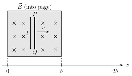
- KCET 2026Set C21 markMCQQ.In the figure shown, the conductor PQ of length l is moved from x=0 to x=b and then up to x=2b with a constant velocity v. A uniform magnetic field B is perpendicular to the plane of the paper and extends from x=0 to x=b and it is zero from x>b. The magnitude of emf induced in the conductor is
 (A) Blx;0≤x<b
(B) Zero; 0≤x<b
(C) Blv;0≤x≤b
(D) Blv;b≤x<2b
(A) Blx;0≤x<b
(B) Zero; 0≤x<b
(C) Blv;0≤x≤b
(D) Blv;b≤x<2b›Reveal solutionSolution
The motional emf induced in a conductor of length l moving with velocity v perpendicular to a uniform magnetic field B is ε=Bvl, and it exists only while the conductor is actually within the field region.
Step 1 — Emf while PQ is inside the field region (0≤x≤b)
While PQ moves from x=0 to x=b, it is continuously within the uniform field B, moving with constant velocity v perpendicular to B. The motional emf is
ε=Bvl
This value does not depend on the position x within the field region — it is the same throughout, since B, v and l are all constant there.
Step 2 — Emf beyond the field region (x>b) …
- KCET 2024Set D-21 markMCQQ.A moving electron produces (A) only electric field (B) both electric and magnetic field (C) only magnetic field (D) neither electric nor magnetic field
›Reveal solutionSolution
A charge always carries an electric field; motion of that charge is a current, which additionally creates a magnetic field.
Step 1 — The electric field is always there
An electron carries charge −e. By Coulomb's law, any charge sets up an electric field in the surrounding space:
E=4πϵ01r2∣q∣
Nothing in this expression depends on whether the charge is moving. Setting the electron in motion does not remove its charge, so the electric field does not vanish — it merely becomes time-varying at a fixed observation point (and, for a uniformly moving charge, gets distorted relative to the static Coulomb field). So options (C) and (D) are ruled out immediately.
Step 2 — Motion adds a magnetic field
A charge q moving with velocity v is, by definition, an element of current. The Biot–Savart law for a point charge gives the magnetic field it produces:
B=4πμ0r2qv×r^ …
- COMEDK 2024Set 2024-A1 markMCQQ.A metallic rod of length 'a' is rotated with an angular frequency of 0.2 rads−1 about an axis normal to the rod passing through its one end. A constant and uniform magnetic field of 'B' T parallel to the axis exists everywhere. The emf developed across the ends of the rod is (A) 10Ba2 (B) 5Ba2 (C) 50Ba2 (D) 2Ba2
›Reveal solutionSolution
A rod of length a spinning at ω=0.2 rad s−1 about one end in field B generates ε=21Bωa2=10Ba2.
For a rod rotating about an axis through one end, perpendicular to the rod, with B parallel to the axis, the motional emf is
ε=21Bωa2. …
- COMEDK 2024Set 2024-M1 markMCQQ.A metallic rod of 2 m length is rotated with a frequency 100 Hz about an axis passing through the centre of the circular ring of radius 2 m. A constant magnetic field 2 T is applied parallel to the axis and perpendicular to the length of the rod. The emf developed across the ends of the rod is : (A) 800 π volt (B) 1600 π volt (C) 1600 volt (D) 400 π volt
›Reveal solutionSolution
The rod spans centre-to-rim (L=2 m) and rotates about one end, so ε=21BωL2=800π V — option (A).
Concept
When a rod of length L rotates with angular frequency ω about an axis through one end, in a magnetic field B parallel to that axis, each element dr at radius r moves at speed v=ωr and contributes dε=Bvdr=Bωrdr. Integrating from 0 to L:
ε=∫0LBωrdr=21BωL2.
Here the axis passes through the centre of the ring and the rod length equals the ring radius, so the rod extends from the centre (on the axis) to the rim — it is rotating about one end with L=2 m.
Solution
- Angular frequency:
ω=2πf=2π(100)=200π rads−1.
- Motional emf about one end: …
- KCET 2023Set A-31 markMCQQ.A positively charged particle of mass m is passed through a velocity selector. It moves horizontally rightward without deviation along the line y=qB2mv with a speed v. The electric field is vertically downwards and magnetic field is into the plane of the paper. Now, the electric field is switched off at t=0. The angular momentum of the charged particle about origin O at t=qBπm is (A) qB32mE2 (B) zero (C) qB2mE3 (D) qB3mE2
›Reveal solutionSolution
t=qBπm is exactly half the cyclotron period, so the particle completes a semicircle and recrosses the horizontal axis through O moving along it; there r and v are collinear, so L=m(r×v)=0 - option (B).
Reasoning
With the electric field switched off, only the magnetic field acts and the particle moves on a circle of radius r=qBmv with cyclotron period
T=qB2πm.
The given instant
t=qBπm=2T
is half a period, so the particle traverses a semicircle to the diametrically opposite point of its path. …
- KCET 2023Set A-31 markMCQQ.A metallic rod of length 1 m held along east-west direction is allowed to fall down freely. Given horizontal component of earth’s magnetic field BH=3×10⁻⁵ T. The emf induced in the rod at an instant t=2 s after it is released is (Take g=10 ms−2) (A) 3×10⁻³ V (B) 3×10⁻⁴ V (C) 6×10⁻³ V (D) 6×10⁻⁴ V
›Reveal solutionSolution
A falling rod cuts the horizontal component of Earth’s magnetic field, generating motional emf. The induced emf at t=2 s is 6×10⁻⁴ V.
The key idea is motional emf: when a conductor moves perpendicular to a magnetic field, the free charges inside experience a magnetic force that pushes them to one end, creating a potential difference. For a rod of length l moving with velocity v perpendicular to a uniform field B, the induced emf is E=Blv.
Here the rod is falling freely under gravity, so its velocity increases linearly with time. The rod is oriented east-west, and the horizontal component of Earth’s field is given — that’s the component the rod cuts as it falls vertically. The vertical component of Earth’s field would be parallel to the rod’s motion and doesn’t contribute to the emf (since v and B would be parallel, giving zero cross product). So we only need BH.
-
Find the velocity after 2 seconds.
The rod is released from rest and falls freely with g=10 m/s2.
v=gt=10×2=20 m/s (downward).
-
Identify the effective field and length.
Rod length l=1 m.
Horizontal component BH=3×10⁻⁵ T. …
-
- COMEDK 2023Set 2023-E1 markMCQQ.A metallic rod of 10 cm is rotated with a frequency 100 revolution per second about an axis perpendicular to its length and passing through its one end in uniform transverse magnetic field of strength 1 T. The emf developed across its ends is: (A) 628 V (B) 3.14 V (C) 31.4 V (D) 6.28 V
›Reveal solutionSolution
A rod rotating about one end in a field B develops ε=21BωL2=π≈3.14 V.
For a rod of length L rotating with angular velocity ω about an axis through one end, perpendicular to a field B:
ε=21BωL2. …
- KCET 2020Set A-11 markMCQQ.A potentiometer has a uniform wire of length 5 m. A battery of emf 10 V and negligible internal resistance is connected between its ends. A secondary cell connected to the circuit gives balancing length at 200 cm. The emf of the secondary cell is (A) 4 V (B) 6 V (C) 2 V (D) 8 V
›Reveal solutionSolution
The emf of the secondary cell is found by the ratio of the balancing length to the total length of the potentiometer wire, multiplied by the total voltage across the wire. The answer is 4 V.
The key idea behind a potentiometer is that the potential drop across a uniform wire is directly proportional to its length. Since the wire has uniform cross-section and material, and a steady current flows through it, the voltage per unit length (the potential gradient) is constant. When you connect a secondary cell in the circuit, you slide the jockey until the galvanometer shows zero deflection — that balancing length tells you the emf of the cell equals the potential drop across that portion of the wire.
So the problem reduces to: if the full 5 m wire carries 10 V, then each metre carries 2 V. At a balancing length of 200 cm (which is 2 m), the emf of the secondary cell is simply the voltage across those 2 m.
Let’s go through it step by step.
- Find the potential gradient The total length of the potentiometer wire is L=5 m. The total potential difference across it is V=10 V (the battery’s emf, since internal resistance is negligible). The potential gradient k (voltage per unit length) is:
k=LV=5 m10 V=2 V/m
- Interpret the balancing length The balancing length is given as l=200 cm=2 m. At this point, the potential drop across the wire from the start to the jockey exactly equals the emf E of the secondary cell. So:
E=k×l=(2 V/m)×(2 m)=4 V
- Check the logic …
- KCET 2020Set A-11 markMCQQ.The current in a coil of inductance 0.2 H changes from 5 A to 2 A in 0.5 sec. The magnitude of the average induced emf in the coil is (A) 0.6 V (B) 1.2 V (C) 30 V (D) 0.3 V
›Reveal solutionSolution
The average induced emf is found using Faraday’s law: E=−LΔtΔI. Substituting L=0.2 H, ΔI=−3 A, Δt=0.5 s gives magnitude 1.2 V. The correct option is (B).
The key idea here is self-induction. When the current through a coil changes, the magnetic flux linked with the coil itself changes, inducing an emf that opposes the change (Lenz’s law). The magnitude of this induced emf is proportional to the rate of change of current, with the constant of proportionality being the inductance L.
Why does this work? Faraday’s law for a coil says induced emf E=−dtdΦ. For a single coil, the flux Φ is proportional to the current: Φ=LI, so dtdΦ=LdtdI. Hence E=−LdtdI. For a finite time interval, the average induced emf uses the average rate of change: Eavg=−LΔtΔI.
The negative sign indicates direction (opposing the change), but the question asks for magnitude, so we take the absolute value.
Let’s work it out step by step.
-
Identify the given data
Inductance, L=0.2 H
Initial current, Ii=5 A
Final current, If=2 A
Time interval, Δt=0.5 s
-
Find the change in current
ΔI=If−Ii=2−5=−3 A
The negative sign means current is decreasing. For magnitude, we’ll use ∣ΔI∣=3 A.
-
Apply the formula for average induced emf
Eavg=−LΔtΔI
Substitute the values:
Eavg=−0.2×0.5(−3)
The two negatives cancel:
Eavg=0.2×0.53
-
Simplify the arithmetic
0.53=6
So Eavg=0.2×6=1.2 V …
-
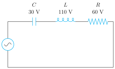
- KCET 2020Set A-11 markMCQQ.In the given circuit the peak voltages across C, L and R are 30 V, 110 V and 60 V respectively. The rms value of the applied voltage is
 (A) 100 V
(B) 200 V
(C) 70.7 V
(D) 141 V
(A) 100 V
(B) 200 V
(C) 70.7 V
(D) 141 V›Reveal solutionSolution
In a series LCR circuit, the applied peak voltage is the phasor sum of the individual peak voltages (not the arithmetic sum). Here, the peak applied voltage is 602+(110−30)2=100 V, so its rms value is 100/2≈70.7 V. The correct option is (C).
The trap in this problem is to simply add the three peak voltages: 30+110+60=200 V. That would be true only if all voltages were in phase — but in a series LCR circuit, the voltages across the inductor and capacitor are 180∘ out of phase with each other, and both are 90∘ out of phase with the resistor voltage. So we must use phasor addition.
-
Identify the phase relationships.
In a series LCR circuit driven by an AC source, the current is the same through all components.
- The voltage across the resistor, VR, is in phase with the current.
- The voltage across the inductor, VL, leads the current by 90∘.
- The voltage across the capacitor, VC, lags the current by 90∘. Therefore, VL and VC are exactly opposite in phase (180∘ apart). Their net effect is the difference VL−VC (or VC−VL, depending on which is larger).
-
Find the net reactive voltage.
Given: VL=110 V (peak), VC=30 V (peak).
Since they oppose each other, the net reactive peak voltage is:
Vreactive=∣VL−VC∣=∣110−30∣=80 V
- Combine with the resistive voltage using phasor addition. The resistor voltage VR=60 V (peak) is at 90∘ to the net reactive voltage. So the total applied peak voltage Vpeak is the hypotenuse of a right triangle: Vpeak=VR2+(VL−VC)2=602+802=3600+6400=10000=100 V …
-
- KCET 2019Set A-11 markMCQQ.A circular current loop of magnetic moment M is in an arbitrary orientation in an external uniform magnetic field B. The work done to rotate the loop by 30° about an axis perpendicular to its plane is (A) MB (B) 32MB (C) 2MB (D) Zero
›Reveal solutionSolution
The axis of rotation is the direction of M itself, so M never turns relative to B; the potential energy doesn't change, so no work is done.
Step 1 — Potential energy of a magnetic dipole in a uniform field.
U(θ)=−M⋅B=−MBcosθ
where θ is the angle between the magnetic moment M and the field B. The work done by an external agent in reorienting the loop is
W=ΔU=U(θ2)−U(θ1)=−MB(cosθ2−cosθ1)
So work depends only on how θ changes — nothing else.
Step 2 — Where does M point?
For a planar current loop of area A carrying current I,
M=IAn^
where n^ is the unit normal to the plane of the loop (right-hand rule). M is perpendicular to the plane, i.e. along the axis of the loop.
Step 3 — Read the rotation axis carefully (this is the whole trick).
The loop is rotated about an axis perpendicular to its plane — that axis is precisely the direction of n^, i.e. of M.
Rotating a vector about its own direction does nothing to it:
Mfinal=Minitial
The circular loop simply spins in its own plane; the current distribution is symmetric about that axis, so the loop's magnetic state is completely unaltered. …
- KCET 2019Set A-11 markMCQQ.Consider the situation given in figure. The wire AB is slid on the fixed rails with a constant velocity. If the wire AB is replaced by a semicircular wire, the magnitude of the induced current will (A) increase (B) remain same (C) decrease (D) increase or decrease depending on whether the semicircle bulges towards the resistance or away from it
›Reveal solutionSolution
Motional emf uses the effective (straight-line, end-to-end) length between the rails, not the arc length of the wire — so bending the slider into a semicircle changes nothing.
Step 1 — The emf as a line integral.
For a wire moving with uniform velocity v in a uniform field B, the emf is
ε=∫AB(v×B)⋅dl
Because v and B are both constant, the vector v×B is a constant vector and can come outside the integral:
ε=(v×B)⋅∫ABdl=(v×B)⋅LAB
where LAB is simply the displacement vector from A to B — the straight line joining the two rail contact points. The path taken between A and B is irrelevant.
Step 2 — Apply it to the semicircular wire.
The wire still touches the same two rails, so A and B (and hence LAB, of magnitude ℓ = rail separation) are unchanged. Therefore
ε=Bℓv(unchanged)
Step 3 — Cross-check with Faraday's law. …
🎓Unlock everything free for 14 days
- ✓Full step-by-step solutions
- ✓Concept-first explanations
- ✓Methods, shortcuts & mistakes
- ✓PYQ mapping + timed mock tests
Full access for 14 days. No credit card required.