Q.Figure 7.17 shows a series LCR circuit connected to a variable frequency 230 V source. L=5.0 H, C=80 μF, R=40 Ω.
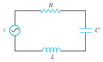
🔒You're viewing a preview — the full solution, concept, methods & PYQ mapping are locked.
🔒 Start your 14-day free trial to unlock the full solution →Concept understanding — Resonance in AC Circuits
Resonance in AC Circuits
A series circuit containing a resistor R, an inductor L and a capacitor C driven by an AC source exhibits resonance — a sharp condition at which the circuit responds most strongly.
The Competing Reactances
In a series RLC circuit the inductor and capacitor oppose the current in opposite senses. Their reactances are
XL=ωL,XC=ωC1
where ω=2πf is the angular frequency. As frequency rises, XL grows while XC shrinks. The total impedance is
Z=R2+(XL−XC)2
The Resonance Condition
At one special frequency the two reactances become exactly equal and cancel:
XL=XC⇒ω0L=ω0C1⇒ω0=LC1
The corresponding resonant frequency is
f0=2πLC1
At this frequency the impedance falls to its minimum, Z=R (purely resistive), so the current reaches its maximum value
Imax=RVrms
Because the reactances cancel, the source voltage and current are exactly in phase — the power factor is 1 at resonance.
Physical Picture
At resonance energy sloshes back and forth entirely between the inductor's magnetic field and the capacitor's electric field, cycle after cycle. The source only has to make up the small amount of energy lost as heat in R. This is the electrical analogue of a swing pushed at its natural frequency: a small periodic drive builds a large oscillation.
Sharpness and the Q-factor
How sharply the current peaks around f0 is measured by the quality factor:
Q=Rω0L=R1CL
A large Q (small R) gives a tall, narrow resonance curve — the circuit is highly selective, responding to a very narrow band of frequencies. A small Q gives a broad, flat peak.
Why It Matters …
Why this formula?
Resonance in AC Circuits: Why the Key Formulas Hold
Resonance in an AC circuit occurs when the inductive reactance (XL) and capacitive reactance (XC) exactly cancel each other out. Let's build the understanding step-by-step.
1. The Core Condition for Resonance
Consider a series RLC circuit (resistor R, inductor L, capacitor C) driven by an AC voltage source V=V0sin(ωt).
The total impedance Z of the series combination is:
Z=R+j(XL−XC)
where:
- XL=ωL (inductive reactance)
- XC=ωC1 (capacitive reactance)
- j=−1
Why resonance happens:
The circuit "wants" to let maximum current flow. The opposition to current comes from both resistance and reactance. But reactance can be negative (capacitive) or positive (inductive). When they are equal in magnitude but opposite in sign, they cancel:
XL=XC
This is the fundamental condition — not a formula to memorize, but a logical consequence of impedance minimization.
2. Deriving the Resonant Frequency
From XL=XC:
ωL=ωC1
Multiply both sides by ω:
ω2LC=1
Thus:
ω0=LC1
Since ω=2πf, the resonant frequency in hertz is:
f0=2πLC1
Why this makes sense:
- A larger L or C means the circuit takes longer to "oscillate" — lower frequency.
- A smaller L or C means faster oscillations — higher frequency.
- The product LC controls the natural time scale of the circuit.
3. What Happens at Resonance — Key Consequences
(a) Impedance is Minimum (Purely Resistive)
At resonance, XL−XC=0, so:
Z=R+j(0)=R
Why: The reactive parts cancel, leaving only the resistance. The circuit behaves like a pure resistor.
(b) Current is Maximum
From Ohm's law for AC:
I=ZV
At resonance, Z=R (minimum possible), so current is maximum:
Imax=RV
Why: The opposition to current is smallest when reactance cancels.
(c) Voltage Across L and C Can Be Very Large
The voltage across the inductor:
VL=I⋅XL=RV⋅ω0L
The voltage across the capacitor:
VC=I⋅XC=RV⋅ω0C1
Since XL=XC at resonance, VL=VC in magnitude, but they are 180° out of phase — they cancel each other in the loop.
Why this is important:
If R is small, VL and VC can be many times larger than the source voltage V. This is called voltage magnification — a key concept for tuned circuits and filters.
--- …
Concept: Resonance in AC Circuits — at resonance, the inductive reactance equals the capacitive reactance (XL=XC), making the impedance purely resistive and minimum.
Reasoning:
-
Resonant frequency:
ω0=LC1=5.0×80×10−61=4×10−41=0.021=50 rad/s
Frequency f0=2πω0=2π50≈7.96 Hz.
-
Impedance and current at resonance:
Z=R=40 Ω (since XL=XC).
Peak voltage V0=2302 V, so I0=RV0=402302≈8.13 A.
RMS current Irms=40230=5.75 A.
-
RMS potential drops:
VR=IrmsR=5.75×40=230 V.
XL=ω0L=50×5.0=250 Ω, so VL=IrmsXL=5.75×250=1437.5 V. …
ω0=1/LC=50 rad/s, i.e. f0≈7.96 Hz; at resonance Z=R=40 Ω and the current amplitude I0=2Vrms/Z≈8.13 A. The rms drops are VR=230 V, VL=VC=1437.5 V, and VL−VC=0 across the LC combination.
(a) Resonant frequency
Resonance occurs when XL=XC, i.e. ω0=LC1:
ω0=5.0×80×10−61=4.0×10−41=50 rad/s,
f0=2πω0=2π50≈7.96 Hz.
(b) Impedance and current amplitude
At resonance XL=XC, so
Z=R2+(XL−XC)2=R=40 Ω.
The current amplitude uses the peak source voltage V0=2×230=325.3 V:
I0=ZV0=40325.3≈8.13 A.
(c) RMS voltage drops
The rms current is Irms=ZVrms=40230=5.75 A, and at resonance XL=XC=ω0L=50×5.0=250 Ω.
VR=IrmsR=5.75×40=230 V, …
Method: Solving a Series LCR Resonance Problem End-to-End
This is the standard three-stage method for any series LCR circuit problem that asks for the resonant frequency, the current/impedance at resonance, and the individual element voltage drops.
Steps
Step 1: Find the resonant frequency from L and C alone.
Resonance occurs when the two reactances cancel, XL=XC, which gives
ω0=LC1,f0=2πω0
Notice this depends only on L and C — never on R or on the source voltage.
Step 2: Use the fact that impedance is purely resistive at resonance.
Because XL=XC at ω0, they cancel in Z=R2+(XL−XC)2, leaving Z=R. This lets you get the peak or rms current directly from Ohm's law for AC:
I0=ZV0=RV0,Irms=RVrms
Always convert between peak and rms with a factor of 2 (V0=2Vrms), and be careful which one the question is actually asking for.
Step 3: Find each element's own reactance at resonance, then its voltage drop. …
- KEAM 2025Set pha-2025-0424A4 marksMCQQ.The a.c circuit exhibiting the phenomenon of resonance has/have the circuit element(s) (A) inductor and resistor (B) capacitor and resistor (C) inductor only (D) capacitor only (E) inductor and capacitor
›Reveal solutionSolution
Electrical resonance needs both energy-storing reactive elements — an inductor and a capacitor.
Resonance in an a.c. circuit occurs when the inductive reactance equals the capacitive reactance:
XL=XC⇒ωL=ωC1⇒ω0=LC1. …
- KEAM 2024Set eng-2024-06054 marksMCQQ.In an LCR resonance circuit at resonance frequency ω0 the quality factor Q is (A) ω0LR (B) ω0LC (C) LRω0 (D) ω0LC (E) Rω0L
›Reveal solutionSolution
The resonance quality factor is Q=Rω0L (equivalently R1L/C).
For a series LCR circuit at resonance ω0=LC1, the quality factor is …
- KEAM 2024Set eng-2024-06074 marksMCQQ.In an LCR series resonance circuit driven by the alternating voltage V=V0sinωt, inductance L = 1 μH, capacitance C = 1 μF and resistance R = 1 kΩ. The resonant angular frequency (in rad s−1) is : (A) 106 (B) 10−6 (C) 1012 (D) 10−12 (E) 1016
›Reveal solutionSolution
ω0=LC1=106 rad s−1.
Resonance in a series LCR circuit occurs at ω0=LC1. With L=1μH=10−6 H and C=1μF=10−6 F, …
- KEAM 2024Set eng-2024-06084 marksMCQQ.In an LCR circuit, at resonance, the value of the power factor is (A) 1 (B) 0 (C) 0.5 (D) 0.75 (E) infinity
›Reveal solutionSolution
At resonance the reactances cancel, the circuit is purely resistive, and cosϕ=1.
In a series LCR circuit at resonance, the inductive and capacitive reactances are equal, XL=XC, so the net reactance is zero and the impedance is purely resistive, Z=R. …
- KEAM 2023Set eng-2023-P1-A14 marksMCQQ.A series LCR circuit consists of a variable capacitor connected to an inductor of inductance 50 mH, resistor of resistance 100Ω and an AC source of angular frequency 500 rad/s. The value of capacitance so that maximum current may be drawn into the circuit is: (A) 60μF (B) 50μF (C) 100μF (D) 80μF (E) 25μF
›Reveal solutionSolution
Maximum current is at resonance, giving C = 1/(omega^2 L) = 80 uF.
Concept and Intuition
In a series LCR circuit the current is maximum at resonance, where the inductive and capacitive reactances cancel and the impedance equals R. The resonance condition is omega^2 L C = 1.
Step-by-Step Solution
- Resonance: omega^2 L C = 1, so C = 1/(omega^2 L).
- Substitute omega = 500 rad/s and L = 50 mH = 0.05 H: C = 1/(500^2 x 0.05). …
🎓Unlock everything free for 14 days
- ✓Full step-by-step solutions
- ✓Concept-first explanations
- ✓Methods, shortcuts & mistakes
- ✓PYQ mapping + timed mock tests
Full access for 14 days. No credit card required.