Q.A 4 μF capacitor is part of a circuit driven by a cell of emf 2.5 V whose internal resistance is 0.5 Ω. Three branches connect the same pair of nodes in parallel: the first branch is the 4 μF capacitor in series with a 10 Ω resistor; the second branch is the 2.5 V cell (internal resistance 0.5 Ω); the third branch is a 2 Ω resistor. In the steady state, the amount of charge on the capacitor plates will be
Concept understanding — Capacitor Network Analysis
Capacitor Network Analysis
Imagine you have a bucket of water and a pipe. The bigger the bucket, the more water it can hold for a given water pressure. A capacitor does the same thing with electric charge — it stores charge when a voltage is applied. The "size" of the bucket is called capacitance (C), measured in farads (F).
Now, what happens when you connect several buckets together with pipes? That's a capacitor network. The analysis is about finding one equivalent bucket (a single capacitor) that behaves exactly like the whole network.
The Core Idea: Charge and Voltage Must Match
When you connect capacitors, two things are always true:
- Charge conservation: Total charge in a closed part of the circuit stays the same unless a battery pushes more in.
- Voltage is shared: The voltage across each capacitor depends on how they're wired.
There are only two basic ways to connect them. Everything else is a combination of these two.
Series Connection: One Path, Shared Charge
Connect capacitors end-to-end, like train cars. The same current flows through each, so each capacitor stores the same amount of charge Q.
But the total voltage across the combination is the sum of the individual voltages:
Vtotal=V1+V2+V3+…
Since V=Q/C for each capacitor, we get:
CeqQ=C1Q+C2Q+C3Q+…
Cancel Q (it's the same everywhere):
Ceq1=C11+C21+C31+…
Intuition: Adding capacitors in series makes the equivalent capacitance smaller than the smallest individual one. Why? Because you're effectively making the "bucket" longer and narrower — harder to fill.
A common mistake: students treat series capacitors like series resistors (adding reciprocals for resistors, but adding directly for capacitors). It's the opposite. For resistors in series: Req=R1+R2. For capacitors in series: 1/Ceq=1/C1+1/C2.
Parallel Connection: Multiple Paths, Same Voltage
Connect capacitors side by side, like buckets with their bottoms connected by a wide pipe. Each capacitor sees the same voltage V across it.
But the total charge stored is the sum of charges on each:
Qtotal=Q1+Q2+Q3+…
Since Q=CV for each:
CeqV=C1V+C2V+C3V+…
Cancel V:
Ceq=C1+C2+C3+…
Intuition: Adding capacitors in parallel makes the equivalent capacitance larger — you're just adding more bucket area. Easy to fill.
| Connection | Equivalent Formula | What happens to Ceq |
|------------|-------------------|----------------------------------|
| Series | 1/Ceq=∑1/Ci | Gets smaller than smallest |
| Parallel | Ceq=∑Ci | Gets larger than largest |
How to Analyze Any Network
- Spot the pattern: Look for capacitors that are clearly in series (only two terminals, no branching between them) or clearly in parallel (both ends connected together).
- Replace step by step: Replace each simple series or parallel group with its equivalent capacitor. Redraw the circuit after each step.
- Repeat until you have one capacitor.
This is exactly like simplifying resistor networks — but with the reciprocal formula for series. If you can do resistor networks, you can do capacitor networks. Just flip the series formula.
A Worked Example
Suppose you have three capacitors: C1=2 μF, C2=3 μF, C3=6 μF. C2 and C3 are in parallel, and that combination is in series with C1.
Step 1: Parallel group first.
C23=C2+C3=3+6=9 μF
Step 2: Now C1 (2 μF) is in series with C23 (9 μF).
Ceq1=21+91=189+2=1811
Ceq=1118 μF≈1.64 μF
Notice: the final equivalent is smaller than the smallest individual capacitor (2 μF). That's the series effect.
The Deeper Reason: Energy and Symmetry
Capacitors store energy: U=21CV2. In a network, energy is conserved (ignoring losses). The equivalent capacitor must store the same total energy as the original network for the same applied voltage. That's why the formulas work — they're derived from charge and voltage matching, which guarantees energy matching.
When you see a complex network, always ask: "Which capacitors share the same voltage?" (parallel) and "Which capacitors share the same charge?" (series). That's the entire analysis.
Final takeaway: Capacitor network analysis is just systematic application of two rules — series (same charge, voltages add) and parallel (same voltage, charges add). Reduce step by step, and you can handle any network.
Reducing series and parallel capacitor networks to a single equivalent capacitance is a standard numerical skill from the NCERT Class 12 Physics chapter on electrostatic potential and capacitance, tested every year in CBSE boards and JEE Main. Searches for "capacitors in series and parallel formula class 12 physics important questions" will find this step-by-step reduction method is exactly what board exam solutions use.
In the steady state no current flows through the capacitor branch, so the 10 Ω resistor in series with it drops no voltage. The full node-to-node voltage (the cell's terminal voltage, 2 V) sits across the capacitor, giving Q=CV=8 μC.
With the capacitor fully charged, current only circulates through the cell and the 2 Ω resistor: I=2.5/(2+0.5)=1 A, so the terminal voltage is 2.5−1×0.5=2 V. That 2 V appears entirely across the capacitor, so Q=4 μF×2 V=8 μC.
Option (d): 8 μC.
A fully charged capacitor passes no steady current, so its branch is 'dead'. Current only circulates through the cell and the 2 Ω resistor, fixing the cell's terminal voltage at 2 V. That 2 V lies entirely across the capacitor (the series 10 Ω has zero drop), so Q=CV=4 μF×2 V=8 μC.
Concept
In a DC steady state a capacitor is fully charged and blocks further current. Any resistor in series with it therefore carries no current and develops no potential drop.
Why this approach
Because the capacitor branch carries no current, the voltage across it equals the voltage the cell maintains between the two nodes (its terminal voltage), which is set by the resistive loop the current actually flows in.
Steps
- Current path: only the cell (emf 2.5 V, internal resistance 0.5 Ω) and the 2 Ω resistor form a closed conducting loop. I=R+rE=2+0.52.5=1 A.
- Terminal (node-to-node) voltage: V=E−Ir=2.5−(1)(0.5)=2 V (equivalently the drop I×2 Ω=2 V).
- The capacitor-plus-10 Ω branch spans these same two nodes. No current ⇒ no drop across the 10 Ω ⇒ the whole 2 V is across the capacitor.
- Q=CV=4 μF×2 V=8 μC.
Why the distractors fail: (a) 0 needs zero node voltage;
(b) 4 μC uses V=1 V;
(c) 16 μC uses V=4 V — none matches the actual 2 V.
Q=8 μC — option (d).
Method: Finding Capacitor Charge in a DC Steady-State Circuit
This method finds the charge on a capacitor embedded in a resistor network fed by a battery, once the circuit has settled into steady state.
Steps
Step 1: Recognise that a fully charged capacitor blocks steady current
In steady state (a long time after switch-on), a capacitor is fully charged and no current flows through its branch — it behaves like an open switch for DC. Any resistor placed purely in series with it therefore also carries zero current.
Step 2: Consider the circuit with the capacitor branch removed
Solve for currents using only the remaining resistive loop(s), treating the capacitor's branch as disconnected for the purpose of finding currents.
Step 3: Find the potential difference across the two nodes the capacitor branch spans
Apply Ohm's law / Kirchhoff's voltage law to the surviving loop to get the current, then the potential difference between the two nodes where the capacitor's branch connects — this is often the source's terminal voltage, E−Ir, when the capacitor branch sits in parallel with the source.
Step 4: That node-to-node voltage lies entirely across the capacitor
Since no current flows in the capacitor's branch, any resistor in series with the capacitor has zero voltage drop across it — so the entire node-to-node voltage from Step 3 appears across the capacitor itself.
Step 5: Compute the charge
Q=C×Vcapacitor
- KEAM 2026Set eng-2026-04184 marksMCQQ.When a parallel combination of 2 capacitors of 100 pF each is connected across a series combination of 2 capacitors of 200 pF each, the effective capacitance is (A) 600 pF (B) 9400pF (C) 200 pF (D) 100 pF (E) 300 pF
›Reveal solutionSolution
The two 100 pF caps in parallel give 200 pF; the two 200 pF caps in series give 100 pF; connecting these two blocks across each other places them in parallel: 200+100=300pF.
Parallel combination of two 100pF:
C1=100+100=200pF
Series combination of two 200pF:
C2=200+200200×200=40040000=100pF
"Connected across" one another means C1 and C2 share the same two terminals — a parallel connection:
Ceff=C1+C2=200+100=300pF
✓Final answerThe correct option is (E).
- KEAM 2025Set eng-2025-04234 marksMCQQ.In a circuit, the capacitance C is connected. The effective capacitance of the circuit can be reduced by (A) introducing a metal plate between the plates of the capacitor (B) introducing a dielectric slab between the plates (C) reducing the potential difference between the plates (D) connecting another capacitor in series with it (E) connecting another capacitor in parallel with it
›Reveal solutionSolution
The effective capacitance is reduced by connecting another capacitor in series with it.
Concept and Intuition
Capacitors in series give a combined capacitance smaller than the smallest individual one, since Ceq1=C11+C21. All the other listed actions either increase capacitance or do not change it.
Step-by-Step Solution
- Series: Ceq1=C1+C′1⇒Ceq<C.
- A metal plate or dielectric increases capacitance; parallel connection increases it; potential difference does not change capacitance.
- Only series reduces it.
Common Mistakes
- Thinking a parallel capacitor reduces capacitance; parallel actually adds capacitances.
✓Final answerThe correct option is (D) — connecting another capacitor in series with it.
ANSWER: D
- KEAM 2025Set eng-2025-04264 marksMCQQ.The equivalent capacitance of n capacitors of equal capacitance when connected in series and parallel are respectively 0.4 μF and 10 μF. The capacitance of each capacitor is (A) 2 μF (B) 4 μF (C) 5 μF (D) 6 μF (E) 1 μF
›Reveal solutionSolution
For n equal capacitors, series gives C/n and parallel gives nC. Multiplying the two results eliminates n: C2=0.4×10=4, so C=2 μF.
Series equivalent:
nC=0.4 μF
Parallel equivalent:
nC=10 μF
Multiply the two equations:
nC×nC=C2=0.4×10=4
C=2 μF
(Then n=C/0.4=5, consistent with nC=10.)
✓Final answerThe correct option is (A).
- KEAM 2025Set pha-2025-0424F4 marksMCQQ.Three capacitors each of capacitance 12 μF, are connected in series. When this combination is connected to a battery of 12 V, the charge drawn from the battery is (A) 32 μC (B) 24 μC (C) 48 μC (D) 16 μC (E) 12 μC
›Reveal solutionSolution
Series equivalent =12/3=4μF; charge drawn Q=CeqV=4×12=48μC.
For n equal capacitors C in series, the equivalent capacitance is
Ceq=nC=312μF=4μF.
The charge drawn from the battery (which equals the charge on each series capacitor) is
Q=CeqV=4μF×12V=48μC.
✓Final answerThe correct option is (C).
- KEAM 2024Set eng-2024-06064 marksMCQQ.Three capacitances 1 µF, 4 µF and 5 µF are connected in parallel with a supply voltage. If the total charge flowing through the capacitors is 50 µC, then the supply voltage is (A) 2 V (B) 10 V (C) 6 V (D) 3 V (E) 5 V
›Reveal solutionSolution
Capacitances in parallel add; the supply voltage is total charge divided by total capacitance.
For capacitors in parallel the equivalent capacitance is the sum:
C=1+4+5=10 μF.
Using Q=CV with total charge Q=50 μC,
V=CQ=10 μF50 μC=5 V.
✓Final answerThe correct option is (E).
- KEAM 2023Set eng-2023-P1-A14 marksMCQQ.N capacitors, each with 1μF capacitance, are connected in parallel to store a charge of 1 C. The potential across each capacitor is 100 V. If these N capacitors are now connected in series, the equivalent capacitance in the circuit will be: (A) 10−4 F (B) 10−6 F (C) 10−10 F (D) 5×10⁻⁸ F (E) 10−2 F
›Reveal solutionSolution
With N=104 capacitors, the series equivalent is 10−10 F.
Concept and Intuition
First find N from the parallel configuration: total parallel capacitance is Q/V, and it equals N times the individual 1 μF. For identical capacitors in series, the equivalent capacitance is the individual value divided by N.
Step-by-Step Solution
- Parallel: Cpar=VQ=1001=10−2 F.
- N×1 μF=10−2 F ⇒N=104.
- Series: Cser=N1 μF=10410−6=10−10 F.
Common Mistakes
- Multiplying instead of dividing by N for the series combination.
✓Final answerThe correct option is (C) - 10−10 F.
ANSWER: C
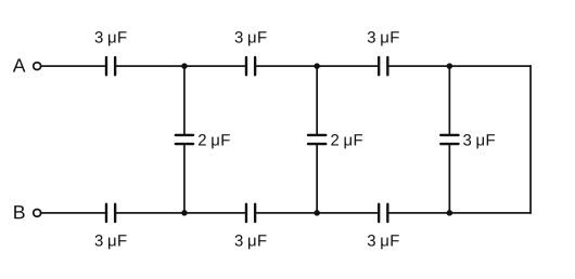
- KEAM 2022Set eng-2022-P1-A14 marksMCQQ.The effective capacitance between A and B in the given figure is [FIGURE] (A) 1.5μF (B) 1μF (C) 3μF (D) 2μF (E) 2.5μF
›Reveal solutionSolution
Solving the symmetric ladder (with the shorted rightmost branch removed) gives about 1 uF between A and B.
Concept and Intuition
The far-right wire ties the two rails together, so the 3 uF capacitor drawn across that shorted junction has both plates at the same node and carries no independent charge. What remains is a symmetric network: A and B feed 3 uF top and bottom rails whose internal junctions are bridged by 2 uF capacitors, terminating at a common right node.
Step-by-Step Solution
- Short the right ends: the rightmost 3 uF vertical branch is bypassed and drops out.
- Set A = V, B = 0; by top-bottom symmetry the right node sits at V/2.
- Write charge-balance (Kirchhoff) equations at the internal top nodes P1, P2, using V_Q = V - V_P.
- Solving gives V_P1 approx 0.665 V, so charge from A = 3(V - V_P1) approx 1.0 V.
- C_eq = Q/V approx 1.0 uF.
Common Mistakes
- Forgetting that the closing wire short-circuits the rightmost vertical capacitor.
✓Final answerThe correct option is (B) — 1 uF.
ANSWER: B
- KEAM 2021Set eng-2021-P1-A14 marksMCQQ.An air capacitor and identical capacitor filled with dielectric medium of dielectric constant 5 are connected in series to a voltage source of 12V. The fall of potential across C1 and C2 are respectively (A) 2 V and 10 V (B) 10 V and 2 V (C) 6 V and 6 V (D) 4 V and 8 V (E) 8 V and 4 V
›Reveal solutionSolution
The air capacitor drops 10 V and the dielectric one drops 2 V.
Concept and Intuition
Series capacitors carry the same charge Q, so V=Q/C: the smaller capacitor takes the larger voltage. The dielectric raises C2 five-fold, so it takes the smaller share.
Step-by-Step Solution
- C1=C (air), C2=5C (dielectric constant 5).
- Same Q: V1/V2=C2/C1=5.
- V1+V2=12 V with V1=5V2⇒6V2=12⇒V2=2 V, V1=10 V.
Common Mistakes
- Assigning the larger voltage to the higher-capacitance (dielectric) capacitor.
✓Final answerThe correct option is (B) — 10 V and 2 V.
ANSWER: B
🎓Unlock everything free for 14 days
- ✓Full step-by-step solutions
- ✓Concept-first explanations
- ✓Methods, shortcuts & mistakes
- ✓PYQ mapping + timed mock tests
Full access for 14 days. No credit card required.