Physics · Ch 4 — Moving Charges and Magnetism
Torque on a Rectangular Current Loop in a Uniform Magnetic Field
Torque on a Rectangular Current Loop in a Uniform Magnetic Field
Why a Current Loop Experiences Torque (Not Net Force)
A rectangular loop carrying a steady current in a uniform magnetic field feels no net force but does experience a torque. This is analogous to an electric dipole in a uniform electric field. The torque arises because equal and opposite forces act on opposite sides of the loop, forming a couple.
Case 1: Loop Plane Parallel to ()
- The magnetic field lies in the plane of the loop.
- Arms AD and BC are parallel to → no force on them.
- Arm AB (length ) is perpendicular to → force acts into the plane.
- Arm CD (length ) is also perpendicular to → force acts out of the plane.
Magnitudes of these forces:
These two forces are equal, opposite, and not collinear — they form a couple. The perpendicular distance between them is (the width of the loop). The torque magnitude is:
where is the area of the rectangular loop.
Case 2: Loop Plane at an Angle to
Let be the angle between the normal to the loop (area vector ) and the magnetic field .
(When the plane is parallel to , .)
- Forces on arms BC and DA are equal, opposite, and collinear along the axis → cancel, giving no net force or torque.
- Forces on arms AB and CD still have magnitude , but now the perpendicular distance between them is reduced to .
Torque magnitude becomes:
As , the perpendicular distance goes to zero → forces become collinear → torque vanishes.
Magnetic Moment and Vector Form of Torque
Define the magnetic moment of the current loop:
where is the area vector (direction given by right-hand thumb rule: curl fingers along current, thumb points along ). Its SI unit is .
The torque in both cases is compactly written as:
Magnitude: , where .
This is analogous to the torque on an electric dipole: .
Equilibrium and Stability
- Stable equilibrium: parallel to (). Any small rotation produces a torque that restores the original orientation. …
Drawn by us to help you understand the concept clearly, and verified to make sure it's accurate. For exams, practice from your textbook's own diagram.
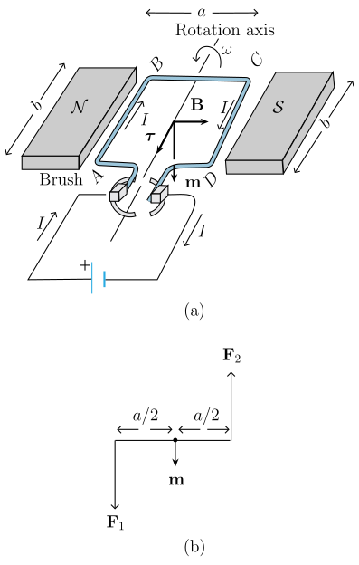
What Fig. 4.18 Shows
Panel (a) depicts a rectangular coil ABCD suspended between the north (N) and south (S) poles of a magnet. The uniform magnetic field B points horizontally from left to right (bold arrow). The coil carries a steady current I, with arrows indicating its direction around the loop. A vertical rotation axis (marked with ω at the top) passes through the centre. The coil has width a (top side) and side length b. The magnetic moment m points vertically downward, and the torque τ acts along the axis, tending to rotate the coil anticlockwise. At the bottom, a brush and a cell with a '+' sign supply the current.
Panel (b) is a view looking along the AD end of the coil. It shows two forces: F₂ acting upward and F₁ acting downward, each located a distance a/2 from the centre. The magnetic moment m points downward between these forces, illustrating the couple that produces the torque.
Physical Idea
The figure demonstrates that a current-carrying rectangular loop in a uniform magnetic field experiences no net force but does experience a torque. This torque arises because the forces on the two arms perpendicular to the field (AB and CD) are equal in magnitude but opposite in direction and are not collinear — they form a couple. The arms parallel to the field (AD and BC) experience no force. This behaviour is analogous to an electric dipole in a uniform electric field.
Key Formula Developed
The magnitude of the torque on the loop when the plane of the loop is along the magnetic field (as in Fig. 4.18) is:
where:
- = current in the loop,
- = area of the rectangular loop,
- = magnitude of the uniform magnetic field.
For the general case where the plane of the loop makes an angle with the field (or equivalently, the normal to the loop makes angle with B), the torque becomes:
This can be written as a vector cross product using the magnetic moment m: …
Drawn by us to help you understand the concept clearly, and verified to make sure it's accurate. For exams, practice from your textbook's own diagram.
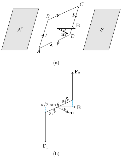
Figure 4.19 extends the simpler case of a rectangular loop in a plane parallel to the magnetic field (Fig. 4.18) to the general situation where the loop is tilted. The figure has two parts:
Panel (a) shows the full 3D view. The rectangular coil ABCD sits between the north (left) and south (right) pole pieces. The uniform magnetic field is horizontal, drawn as bold arrows pointing from N to S. The plane of the coil is rotated so that its area vector (or the normal to the coil) makes an angle with . The magnetic moment is drawn along the same direction as , and the angle is marked between and . The current flows around the loop in the direction ABCD.
Panel (b) is a top view looking down along the AD axis. The loop edge appears as a short bar tilted at angle to the horizontal. The forces on the arms AB and CD are shown: points upward and points downward, forming a couple (a pure torque). The perpendicular distance between these forces is reduced from (the full side length) to , as indicated by the label "" on each half-arm. The magnetic moment is again shown at angle .
Physical idea: The torque on a current loop in a uniform magnetic field depends on the orientation of the loop. When the plane of the loop is not aligned with , the forces on arms AB and CD are equal in magnitude but not collinear, producing a couple. The effective lever arm is , so the torque is smaller than the maximum value (which occurs when , i.e., the plane of the loop is parallel to ).
Key formula developed from this figure:
The magnitude of the torque on the loop is
where:
- = current in the loop (in amperes)
- = area of the rectangular loop (in m²)
- = magnitude of the uniform magnetic field (in tesla)
- = angle between the area vector (or magnetic moment ) and …