Q.(a) Explain with the help of suitable diagram, the two processes which occur during the formations of a p-n junction diode. Hence define the terms
You're viewing a preview — the full solution, concept, methods & PYQ mapping are locked.
Start your 14-day free trial to unlock the full solution →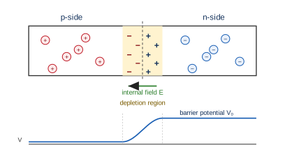
Diffusion + drift depletion region + potential barrier; forward bias lowers the barrier and current flows. (OR: modulation is needed for practical antenna size, adequate radiated power, and to avoid signal mixing; draw carrier, modulating and AM waveforms.)
(a) Formation of a p-n junction. Two processes occur:
- Diffusion: because of the concentration gradient, majority holes diffuse from pn and majority electrons diffuse from np, leaving behind immobile negative acceptor ions on the p-side and positive donor ions on the n-side.
- Drift: these immobile ions set up an electric field (n positive, p negative) that drives minority carriers in the opposite direction (drift). Equilibrium is reached when diffusion and drift currents balance.
- (i) Depletion region: the thin region on either side of the junction that is depleted of free/mobile charge carriers, containing only fixed ionised donors and acceptors.
- (ii) Potential barrier: the built-in potential difference developed across the depletion region (n-side higher, p-side lower) that opposes further diffusion of majority carriers.
(b) Forward bias. Connect the p-side to the + terminal and n-side to the − terminal of a battery. The external field opposes the built-in field, so the depletion width decreases and the barrier potential is reduced. Majority carriers are pushed across the junction, and a large forward current flows that rises steeply once the applied voltage exceeds the barrier (knee) voltage. (Circuit to draw: diode with p to battery +, n to −, in series with a resistor and a milliammeter.)
OR-alternative (need for modulation). …
Unlock everything free for 14 days
- Full step-by-step solutions
- Concept-first explanations
- Methods, shortcuts & mistakes
- PYQ mapping + timed mock tests
Full access for 14 days. No credit card required.