Physics · Ch 7 — Alternating Current
AC Voltage Applied to a Resistor
AC Voltage Applied to a Resistor
AC Voltage Applied to a Resistor
When an alternating voltage is applied across a pure resistor, the current that flows is also alternating. The key result is that the voltage and current are in phase — they reach zero, maximum, and minimum values at exactly the same instant.
Derivation of Current
Consider an AC source producing a sinusoidally varying voltage:
Here:
- is the instantaneous voltage
- is the amplitude (peak value) of the voltage
- is the angular frequency ()
Applying Kirchhoff's loop rule to the circuit (a resistor connected to the AC source):
Solving for the instantaneous current :
Since is constant, we write this as:
where the current amplitude is given by:
This is Ohm's law for AC circuits — it works exactly like the DC case for a resistor.
Phase Relationship
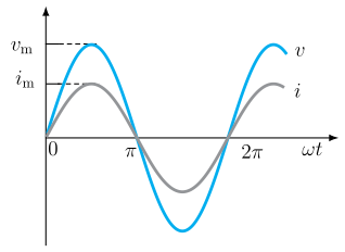
Both and vary sinusoidally. They reach zero, positive maximum, and negative maximum at the same time. Therefore, voltage and current are in phase in a purely resistive AC circuit.
Average Current
The instantaneous current takes both positive and negative values over a cycle. The sum of instantaneous currents over one complete cycle is zero, so the average current is zero. This does not mean zero power dissipation.
Power Dissipation
Joule heating depends on , which is always positive. The instantaneous power is:
The average power over a cycle is:
Using the identity , and noting that the average of over a full cycle is zero:
Thus:
Root Mean Square (RMS) Values
To express AC power in the same form as DC power (), we define the rms current (also called effective current):
Similarly, the rms voltage (effective voltage) is: …
Drawn by us to help you understand the concept clearly, and verified to make sure it's accurate. For exams, practice from your textbook's own diagram.
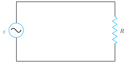
Figure 7.1 shows a simple series circuit consisting of an AC voltage source (drawn as a circle containing a sine-wave symbol, labelled ) on the left, connected by plain conducting wires to a resistor (drawn as a zig-zag element, labelled ) on the right. The top and bottom wires complete the single-loop rectangular path. There are no current arrows.
The physical idea is that a sinusoidally varying voltage drives a sinusoidally varying current through a pure resistor, and the two quantities remain in phase — they reach zero, maximum, and minimum at the same instants.
The textbook uses this figure to derive the key relations:
- The applied AC voltage is
where is the amplitude (peak voltage) and is the angular frequency.
- Applying Kirchhoff’s loop rule gives
so the current is
with current amplitude
This is Ohm’s law for AC — the same form as for DC.
- The instantaneous power dissipated in the resistor is
- Averaging over one cycle gives the average power
where is the rms current (root mean square).
- Similarly, the rms voltage is …
Drawn by us to help you understand the concept clearly, and verified to make sure it's accurate. For exams, practice from your textbook's own diagram.
What the plot shows
The figure is a standard time‑domain plot of two sinusoidal waves on the same set of axes. The horizontal axis is labelled (angular frequency times time), with tick marks at , , and — representing one complete cycle of the alternating quantity. The vertical axis is the amplitude, with the peak of the larger wave marked and the peak of the smaller wave marked .
Two curves are drawn:
- The larger sinusoid represents the instantaneous voltage .
- The smaller sinusoid represents the instantaneous current .
Both curves start at zero at , rise together to their positive peaks near , cross zero together at , dip together to their negative minima, and return to zero at . The key visual fact is that the two waves are perfectly aligned — they reach zero, maximum, and minimum at exactly the same instants. This is what the textbook means by “the voltage and current are in phase.”
Physical idea taught by the figure
For a pure resistor, there is no energy storage (no inductance or capacitance). The opposition to current is purely resistive, given by Ohm’s law. Therefore, the current responds instantaneously to the applied voltage — there is no lag or lead. The figure makes this concrete: at every moment, the ratio is constant and equal to the resistance . The fact that both waves cross zero together shows that when the voltage is zero, the current is also zero; when the voltage is maximum, the current is also maximum. This “in‑phase” behaviour is the defining characteristic of a purely resistive AC circuit.
Key formulas developed with this figure
From the circuit analysis using Kirchhoff’s loop rule, the applied voltage is
and the current through the resistor is
where the current amplitude is
This is Ohm’s law for AC — the same form as for DC, but now relating the amplitudes.
The instantaneous power dissipated is
and its average over one cycle is
To express this in the familiar DC form , the root mean square (rms) current is defined: …
Drawn by us to help you understand the concept clearly, and verified to make sure it's accurate. For exams, practice from your textbook's own diagram.
What the Figure Shows
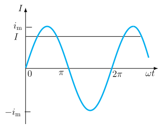
The figure plots the instantaneous alternating current as a function of the phase angle (in radians) on the horizontal axis. The axis is marked at , , and , covering one complete cycle of the sinusoidal waveform. The vertical axis represents the current, with the peak values and clearly labelled at the top and bottom of the oscillation.
A single sine curve oscillates symmetrically between these two extremes. Superimposed on this curve is a horizontal dashed line drawn at a constant level between and the positive peak . This dashed line represents the root mean square (rms) current, denoted by . Its position is at , as stated in the caption.
Physical Idea Taught
The figure visually demonstrates the concept of rms current — a way to express an alternating current in terms of an equivalent direct current that would produce the same average heating effect in a resistor. Since the instantaneous power dissipated in a resistor is , and is always positive, the average power is not zero even though the average current over a cycle is zero. The rms value is the effective value of the ac current, and the dashed line shows how it compares to the peak swing of the waveform.
Key Formula Developed
The textbook derives the relation between the peak current and the rms current :
where:
- is the amplitude (peak value) of the sinusoidal current,
- (or ) is the root mean square current — the constant dc current that would dissipate the same average power in a resistor. …