Physics · Ch 9 — Ray Optics and Optical Instruments
Combination of Thin Lenses in Contact
Combination of Thin Lenses in Contact
Why Combine Lenses?
A single lens has limitations: its focal length is fixed, and it may produce images with aberrations (blurring). By placing two or more thin lenses in contact (their optical centres coinciding), we create a single equivalent lens. This combination allows us to:
- Achieve a desired net focal length (converging or diverging).
- Increase the magnification (product of individual magnifications).
- Improve image sharpness by reducing aberrations.
The key idea: the image formed by the first lens acts as the object for the second lens. Because the lenses are thin and in contact, we treat their optical centres as a single point (P).
Derivation of the Equivalent Focal Length
Consider two thin lenses A and B with focal lengths and , placed in contact. An object is placed at point O, beyond the focus of lens A.
- Image by first lens (A): Using the lens formula for lens A:
Here, $u$ is the object distance from the combination, and $v_1$ is the image distance from lens A.
2. Image by second lens (B): The image formed by lens A serves as a virtual object for lens B. The object distance for lens B is (but with a sign convention, it is taken as negative because the rays appear to diverge from it). The final image is formed at distance from the combination. Applying the lens formula for lens B:
- Adding the equations: Adding the two equations eliminates :
- Equivalent single lens: If the entire combination behaves like a single lens of focal length , then for the same object distance and final image distance , the lens formula would be:
Comparing this with the result from step 3, we get the **combination formula**:
This derivation is valid for any number of thin lenses in contact.
Important Points to Remember
- Sign convention: The sum in the power formula is algebraic. A convex lens contributes positive power; a concave lens contributes negative power. …
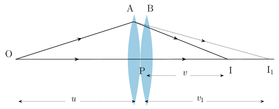
Drawn by us to help you understand the concept clearly, and verified to make sure it's accurate. For exams, practice from your textbook's own diagram.
What the Figure Shows
The diagram depicts two thin lenses, A and B, placed in contact — meaning they are drawn touching each other along a common horizontal axis (the principal axis). Because the lenses are thin and in contact, their optical centres are treated as coinciding at a single point labelled P. The object is placed at point O to the left of the lenses, beyond the focus of the first lens A.
The figure uses ray paths to illustrate the stepwise image formation:
- Lens A alone would form an intermediate image at I₁ (to the right of lens A).
- This intermediate image I₁ then acts as a virtual object for lens B, because the rays from lens A are converging toward I₁ when they strike lens B.
- Lens B then forms the final image at I.
Key distances are marked along the axis:
- u = object distance from the common optical centre P (for lens A)
- v₁ = image distance for lens A (distance from P to I₁)
- v = final image distance from P (for the combination)
The lenses themselves are labelled with their focal lengths: f₁ for lens A and f₂ for lens B.
Physical Idea Taught
The figure teaches that when two thin lenses are placed in contact, the image formed by the first lens becomes the object for the second lens. Even though the intermediate image I₁ is real, it serves as a virtual object for the second lens because the rays are already converging toward it. The final image I is formed by the combined effect of both lenses.
The key insight is that the effective focal length of the combination is not simply the sum or average of the individual focal lengths, but is given by the reciprocal sum formula. This allows the combination to behave as a single equivalent lens.
Key Formulas Developed
For the first lens A:
For the second lens B (using I₁ as virtual object):
Adding these two equations gives:
If the combination is treated as a single lens of focal length , then:
Comparing, we get the effective focal length formula:
In terms of power (where in metres), this becomes:
For any number of thin lenses in contact:
The total magnification of the combination is the product of the individual magnifications:
Symbol Meanings
| Symbol | Meaning | …