Q.Explain the principle and working of RADAR with neat block diagram.
You're viewing a preview — the full solution, concept, methods & PYQ mapping are locked.
Start your 14-day free trial to unlock the full solution →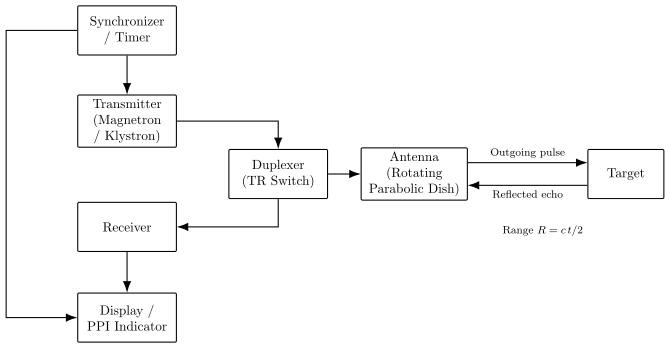
RADAR detects and locates targets by transmitting microwave pulses, timing the delay of their reflected echo, and using the antenna's pointing direction, giving both range and bearing of the target.
Principle
RADAR stands for RAdio Detection And Ranging. It works on the principle that electromagnetic waves in the microwave region, when transmitted toward an object (target), are partly reflected back toward the source as an 'echo'. Since electromagnetic waves travel at the speed of light , the time interval between transmission of a pulse and reception of its echo can be used to compute the distance (range) of the target, because the wave travels to the target and back, covering a total distance in time :
The direction in which the (highly directional) antenna is pointing at the instant the echo is received gives the bearing (angular direction) of the target.
Block diagram (described)
A basic pulsed RADAR system consists of the following blocks, connected in a loop:
- Transmitter: Generates short bursts (pulses) of very high-power microwave-frequency oscillations, typically using a magnetron or klystron oscillator, modulated into brief pulses by a pulse-modulator/timer.
- Duplexer (TR switch): A transmit-receive switch that allows a single antenna to be shared for both transmitting and receiving. During transmission, it connects the antenna to the transmitter and isolates the sensitive receiver from the powerful outgoing pulse; during the (much longer) listening interval between pulses, it connects the antenna to the receiver so that the weak returning echo can be picked up.
- Antenna: A highly directional antenna, typically a rotating parabolic reflector (dish), which concentrates the transmitted energy into a narrow beam and continuously scans the surrounding space; the same antenna receives the reflected echo from whatever direction it is currently pointing.
- Receiver: Amplifies and processes the extremely weak echo signal picked up by the antenna — typically comprising a low-noise RF amplifier, a mixer (to convert to a fixed intermediate frequency), an IF amplifier, and a detector, to recover a usable pulse signal from the tiny returned echo.
- Synchronizer/Timer: Coordinates the timing of the whole system — triggering the transmitter to send out each pulse and simultaneously starting the timing sweep used to measure the return time of the echo, so that the transmitted pulse and received echo can be correctly correlated in time.
- Indicator/Display unit: Displays the processed information to an operator, typically as a Plan Position Indicator (PPI) — a circular CRT display where the radial distance from the centre represents range and the angular position represents bearing, so that the position of detected targets is shown directly on the screen, updated continuously as the antenna scans.
Working
The transmitter generates a high-power microwave pulse under control of the synchronizer. This pulse passes through the duplexer to the antenna, which radiates it as a narrow, directional beam. The antenna continuously rotates (or scans) to cover the surrounding region.
…
Unlock everything free for 14 days
- Full step-by-step solutions
- Concept-first explanations
- Methods, shortcuts & mistakes
- PYQ mapping + timed mock tests
Full access for 14 days. No credit card required.