Physics · Ch 9 — Mechanical Properties of Fluids
Bernoulli's Principle
Bernoulli's Principle
Bernoulli’s Principle
Fluid flow is a complex phenomenon, but for steady or streamline flows we can extract powerful relationships using the conservation of energy. Consider a fluid moving through a pipe whose cross-sectional area changes along its length, and whose height also varies. The fluid is incompressible and flows steadily.
Because the velocity must change when the cross-sectional area changes (from the equation of continuity), a force is required to produce that acceleration. That force comes from the surrounding fluid, which means the pressure must be different in different regions. Bernoulli’s equation gives the general relationship connecting the pressure difference between two points in a pipe to changes in velocity (kinetic energy) and changes in elevation (potential energy). The Swiss physicist Daniel Bernoulli first derived this relationship in 1738.
Derivation of Bernoulli’s Equation
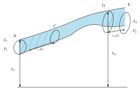
Consider the flow at two regions of the pipe, labelled region 1 (between B and C) and region 2 (between D and E). Focus on the fluid that initially lies between B and D. In an infinitesimal time interval , this fluid moves.
Let be the speed at B and the speed at D. In time , the fluid initially at B moves a distance to C (this distance is small enough that we can assume the cross-section is constant along BC). In the same interval, the fluid initially at D moves to E, a distance .
Pressures and act on the plane faces of areas and that bound the two regions.
Work done on the fluid
At the left end (BC), the force is and it acts through a distance , so the work done on the fluid is
where is the volume that passes through region 1 in time .
From the equation of continuity, the same volume passes through region 2. At the right end (DE), the fluid does work on its surroundings (the force acts opposite to the direction of motion of the fluid), so the work done on the fluid at this end is negative:
The total work done on the fluid is therefore
Where does this work go?
Part of this work changes the kinetic energy of the fluid, and part changes its gravitational potential energy.
Let be the density of the fluid. The mass passing through the pipe in time is
The change in gravitational potential energy as the fluid moves from height to height is
The change in kinetic energy is
Applying the work-energy theorem
The work-energy theorem states that the total work done on a system equals its change in total mechanical energy (kinetic plus potential). Applying it to this volume of fluid:
Divide every term by :
Rearrange to bring all terms for point 1 to one side and all terms for point 2 to the other:
This is Bernoulli’s equation.
Since points 1 and 2 are any two locations along the pipeline, we can write the general form:
Statement of Bernoulli’s Principle
As we move along a streamline, the sum of three quantities remains constant:
- the pressure ,
- the kinetic energy per unit volume ,
- the potential energy per unit volume .
In other words, for a steady, incompressible, non-viscous flow along a streamline:
Limitations and Assumptions
The derivation of Bernoulli’s equation uses the work-energy theorem, which assumes that no energy is lost due to friction. In real fluids, however, energy is lost because of internal friction between layers of the fluid that flow at different velocities. These layers exert frictional forces on each other, converting some kinetic energy into heat. This property of fluids is called viscosity.
Bernoulli’s equation applies strictly only to non-viscous (zero viscosity) fluids. In viscous fluids, energy losses mean the equation is only approximately true, and corrections are needed.
Another restriction is that the fluid must be incompressible. If the fluid compresses or expands, its elastic energy changes, and that energy is not accounted for in Bernoulli’s equation. …
Drawn by us to help you understand the concept clearly, and verified to make sure it's accurate. For exams, practice from your textbook's own diagram.
Fig. 9.9 is a schematic of a pipe that narrows as it rises. The pipe is drawn in cross-section, so you see its interior. On the left, the pipe is wide (cross-sectional area ) and sits at a height above a reference level (the ground). On the right, the pipe is narrow (area ) and is higher up, at height . The pipe is completely filled with an ideal fluid — incompressible and non-viscous — flowing steadily from left to right.
The figure labels two key locations. At the wide, low end, a point is marked B (on the lower wall) and C (on the upper wall); the pressure there is . At the narrow, high end, points D (lower wall) and E (upper wall) are marked, with pressure . The fluid is moving, so the diagram also shows two hatched (shaded) slabs of fluid. The slab on the left has length — that is the distance the fluid travels in a small time interval at speed . The slab on the right has length , the distance covered in the same at speed . Because the fluid is incompressible, the volume of the left slab () must equal the volume of the right slab (). This is the equation of continuity:
The figure is drawn to teach Bernoulli’s principle — the conservation of energy per unit volume for a flowing fluid. The key idea is that as the fluid moves from the wide, low section to the narrow, high section, three forms of energy change: kinetic energy (because speed changes), gravitational potential energy (because height changes), and the work done by pressure forces. The textbook uses this figure to derive Bernoulli’s equation by applying the work-energy theorem to the fluid between the two hatched slabs.
The derivation goes like this. In time , the left slab moves into the pipe, and the right slab moves out. The net work done on the fluid by the pressure forces is . Using the continuity equation, , so the net work becomes . This work equals the change in mechanical energy of the fluid: the gain in kinetic energy plus the gain in gravitational potential energy . Cancelling from both sides gives:
This is Bernoulli’s equation for an ideal fluid. Each term has units of pressure (energy per unit volume). The three terms are: (static pressure), (dynamic pressure, from kinetic energy), and (hydrostatic pressure, from gravitational potential energy). The equation says that along a streamline, the sum of these three remains constant.
A common mistake is to think Bernoulli’s equation applies only when the pipe is horizontal (). Fig. 9.9 explicitly shows a rising pipe, so the height terms are essential. If you ignore them, you will get the wrong pressure difference. …