Physics · Ch 7 — Alternating Current
AC Voltage Applied to a Capacitor
AC Voltage Applied to a Capacitor
Why a Capacitor Behaves Differently in AC vs DC
In a DC circuit, a capacitor charges quickly and then blocks current completely — the current stops once the capacitor is fully charged.
In an AC circuit, the voltage reverses polarity every half-cycle. So the capacitor is alternately charged and discharged, and charge keeps flowing. The capacitor does not stop the current; it only limits it.
Deriving the Current in a Purely Capacitive AC Circuit
Consider an AC source connected only to a capacitor (no resistor, no inductor).
The source voltage is:
Let be the charge on the capacitor at time . The voltage across the capacitor is:
From Kirchhoff’s loop rule, the source voltage equals the capacitor voltage:
So:
Current is the rate of change of charge:
Using the identity , we get:
where the current amplitude is:
Capacitive Reactance
Compare this with Ohm’s law for a resistor: .
Here, . So the quantity plays the role of resistance. It is called capacitive reactance:
- has units of ohms ().
- It limits the current amplitude, just like resistance does.
- It is inversely proportional to both frequency () and capacitance ().
The current amplitude can then be written as:
Phase Relationship: Current Leads Voltage
From the equations:
- Voltage:
- Current:
The current is radians (90°) ahead of the voltage.
In terms of time, the current reaches its peak one-quarter of a period earlier than the voltage.
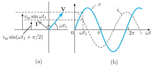
Phasor diagram: The current phasor () is rotated counterclockwise ahead of the voltage phasor ().
Instantaneous and Average Power …
Drawn by us to help you understand the concept clearly, and verified to make sure it's accurate. For exams, practice from your textbook's own diagram.
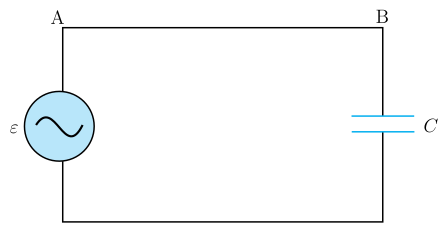
Figure 7.7 shows a simple rectangular loop. On the left side is an ac source (drawn as a circle with a ~ symbol) labelled . On the right side is a capacitor, drawn as two short parallel plates, labelled . The top-left corner of the loop is labelled A, and the top-right corner is labelled B. Conductors complete the loop along the bottom.
The figure teaches the purely capacitive AC circuit — a circuit where only a capacitor is connected to an alternating voltage source. The key physical idea is that the capacitor does not block current completely (as it would in a DC circuit after charging). Instead, it alternately charges and discharges as the AC voltage reverses each half-cycle, allowing a continuous oscillating current to flow.
The textbook uses this figure to derive the relationship between voltage and current. From Kirchhoff’s loop rule, the source voltage equals the capacitor voltage at every instant:
where:
- = instantaneous voltage across the capacitor (and source)
- = peak voltage (amplitude)
- = angular frequency ()
- = time
- = instantaneous charge on the capacitor
- = capacitance
The current is the rate of change of charge: . Differentiating gives:
where the current amplitude is:
and capacitive reactance is defined as: …
Drawn by us to help you understand the concept clearly, and verified to make sure it's accurate. For exams, practice from your textbook's own diagram.
Figure 7.8: Phasor Diagram and Waveform for a Purely Capacitive AC Circuit
This figure has two panels that together show the phase relationship between voltage and current in a circuit containing only a capacitor connected to an AC source.
Panel (a): Phasor Diagram at an instant
- The diagram shows two rotating arrows (phasors) representing the voltage () and the current ().
- The voltage phasor is drawn pointing up-and-right at an angle from the horizontal axis. Its vertical projection is labelled , which is the instantaneous voltage at that instant.
- The current phasor is drawn a quarter-turn counter-clockwise ahead of — it is more vertical than . This represents a phase difference of radians (90°). Its vertical projection is labelled , showing that the current's instantaneous value is ahead of the voltage's by .
- Key idea: The current phasor leads the voltage phasor by as they both rotate counter-clockwise.
Panel (b): Graph of and versus
- The horizontal axis is (in radians), with ticks at , , and .
- The solid curve represents the voltage .
- The dashed curve represents the current .
- The current reaches its maximum value one-quarter of a period earlier than the voltage does. For example, at , the current is already at its peak , while the voltage is zero. This visually confirms that current leads voltage by .
Physical Idea Taught
In a purely capacitive AC circuit, the capacitor does not allow a steady current (as in DC), but it alternately charges and discharges as the AC voltage reverses. Because the current is the rate of change of charge (), and the charge on the capacitor is proportional to the voltage (), the current is proportional to the derivative of the voltage. The derivative of is , which is why the current is ahead of the voltage.
Key Formulas Developed with This Figure
From the textbook derivation using Kirchhoff's loop rule and the relation :
where the current amplitude is:
…