Physics · Ch 6 — Electromagnetic Induction
Motional Electromotive Force
Motional Electromotive Force
What is Motional EMF?
When a conductor moves through a uniform, time-independent magnetic field, an emf is induced across it. This is called motional electromotive force. It arises because the motion changes the magnetic flux enclosed by the circuit, or equivalently, because the moving charges inside the conductor experience a Lorentz force.
Derivation from Faraday's Law (Flux Change)
Consider a rectangular loop where arm (length ) slides to the left with constant speed . The loop is in a uniform magnetic field perpendicular to its plane.
- Let and .
- Area of loop: .
- Magnetic flux through the loop:
As decreases with time, the flux changes. The induced emf is given by Faraday's law:
Since the rod moves left, (negative because decreases). Substituting:
This is the motional emf:
- = induced emf (V)
- = magnetic field strength (T)
- = length of the moving conductor (m)
- = speed of the conductor perpendicular to (m/s)
Derivation from Lorentz Force (Charge Perspective)
Consider a charge inside the moving rod . The rod moves with speed in magnetic field . The Lorentz force on the charge is:
Direction: towards (using right-hand rule). All charges experience the same force.
Work done to move the charge from to (distance ):
Since emf is work done per unit charge:
…
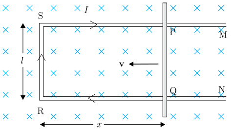
Drawn by us to help you understand the concept clearly, and verified to make sure it's accurate. For exams, practice from your textbook's own diagram.
The figure shows a rectangular conducting loop PQRS placed in a uniform magnetic field directed into the page (represented by symbols). The loop consists of:
- A fixed left side
SRof length (vertical double-headed arrow). - Top and bottom horizontal rails extending to the right, labelled
SPandRQ. - A movable right side
PQ— a thick sliding rod that can move left or right along the rails. - The rod
PQis shown with a bold velocity arrow pointing left, indicating it is being pushed toward the fixed sideSR, thereby decreasing the area of the loop. - The horizontal distance from the fixed side to the rod is labelled (double-headed arrow along the bottom rail).
- A current is shown flowing in the loop (arrow labelled
Ialong the top rail).
The physical idea is motional emf: when a conductor moves in a magnetic field, the free charges inside experience a Lorentz force, leading to an induced emf and current. Here, the rod PQ moves left, reducing the area of the loop. The magnetic flux through the loop is
Since changes with time, the flux changes, inducing an emf. Using Faraday’s law:
The rod moves left with speed , so (because decreases). Substituting gives the motional emf:
Here:
- = magnitude of uniform magnetic field (into page)
- = length of the rod
PQ(also the sideSR) - = speed of the rod (magnitude of velocity) …