Physics · Ch 11 — Thermodynamics
Carnot Engine
Carnot Engine
The Carnot Engine: The Ultimate Heat Engine
The central question of practical heat-engine design is this: given a hot reservoir at temperature and a cold reservoir at , what is the maximum possible efficiency, and what cycle of processes achieves it? In 1824, the French engineer Sadi Carnot answered both questions correctly, remarkably, before the First Law of Thermodynamics was even fully established.
The answer begins with a crucial insight. Any real engine has irreversible steps — friction, turbulence, heat flow across a finite temperature difference — and these dissipate useful work, lowering efficiency. The ideal engine, therefore, must be a reversible engine. A process is reversible only if it is both quasi-static and non-dissipative.
Now, a process cannot be quasi-static if there is a finite temperature difference between the system and the reservoir. This forces a specific structure on the reversible engine. Heat must be absorbed from the hot reservoir isothermally (at ) and rejected to the cold reservoir isothermally (at ). That gives us two steps. But to complete a cycle, the working substance must be taken from down to , and then back up from to . What reversible processes can do this without involving any heat reservoirs? Only reversible adiabatic processes — processes with no heat exchange at all. Any other path (like an isochoric one) would require a continuous series of reservoirs between and to keep the process quasi-static, which violates the condition that the engine operates between only two temperatures.
Thus, a reversible heat engine operating between two fixed temperatures must consist of exactly four steps: two isothermal processes and two adiabatic processes. This sequence is called the Carnot cycle, and the engine itself is a Carnot engine.
A Carnot engine is a reversible heat engine operating between two temperatures (hot reservoir) and (cold reservoir). Its cycle consists of two isothermal and two adiabatic processes.
The Carnot Cycle with an Ideal Gas
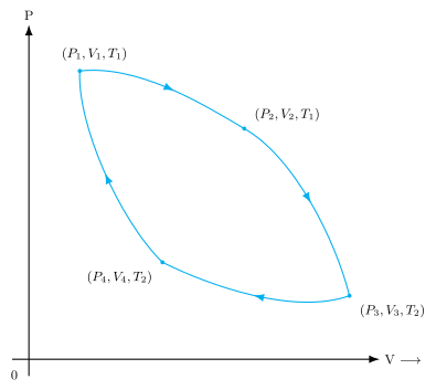
We take an ideal gas as the working substance. The cycle, shown in Fig. 11.9 of the textbook, consists of four reversible steps. Let's go through each one, tracking the state variables .
The sign convention used here: is positive when work is done by the gas on the surroundings. is positive when heat is absorbed by the gas.
Step 1 → 2: Isothermal Expansion at
The gas is in contact with the hot reservoir at . It expands isothermally from to . Since the internal energy of an ideal gas depends only on temperature, for an isothermal process. From the First Law, , so the heat absorbed equals the work done by the gas .
For an isothermal reversible expansion of moles of an ideal gas:
Step 2 → 3: Adiabatic Expansion from to
The gas is now thermally insulated. It expands adiabatically from to . No heat is exchanged (). The gas does work at the expense of its internal energy, so its temperature drops from to .
The work done by the gas in a reversible adiabatic process is given by:
where .
Step 3 → 4: Isothermal Compression at
The gas is placed in contact with the cold reservoir at . It is compressed isothermally from to . Again, . The work done on the gas is , and the heat is released by the gas to the cold reservoir. Since the gas is being compressed (), the work done by the gas is negative. The textbook defines as the work done on the gas by the environment, but in the efficiency calculation, it is subtracted as a negative contribution. The magnitude is:
Note the volume ratio. In step 1→2, the argument is (expansion, ratio > 1, work positive). In step 3→4, the argument is (compression, ratio > 1, but the work is done on the gas, so this quantity represents the magnitude of the heat rejected).
Step 4 → 1: Adiabatic Compression from to
The gas is insulated again. It is compressed adiabatically from back to the initial state . Work is done on the gas, raising its temperature from to . The work done on the gas is:
Notice that has the same magnitude as , but it is work done on the system, so it contributes negatively to the net work done by the system.
Net Work and Efficiency of the Carnot Engine
The total work done by the gas in one complete cycle is the sum of the work in each step, taking signs into account:
Substituting the expressions:
The efficiency of any heat engine is defined as the ratio of net work output to heat input:
Substituting and from Eqs. (11.18) and (11.20):
This expression still contains the volumes. To simplify it, we need a relation between the volume ratios. This comes from the adiabatic steps.
Relating the Volume Ratios
For the adiabatic expansion (step 2→3), the relation holds:
For the adiabatic compression (step 4→1):
From Eqs. (11.24) and (11.25), we get the crucial result:
This is the key geometric property of the Carnot cycle on a - diagram: the expansion ratio of the hot isotherm equals the compression ratio of the cold isotherm.
Substituting Eq. (11.26) into Eq. (11.23), the logarithmic terms cancel, giving the famous result:
This is the maximum possible efficiency for any heat engine operating between two reservoirs at temperatures and . It depends only on the two temperatures, not on the working substance.
Carnot's Theorem: The Proof
The result above leads to two profound statements, collectively known as Carnot's theorem:
- No engine operating between two given temperatures can have an efficiency greater than that of a Carnot engine operating between the same two temperatures.
- The efficiency of a Carnot engine is independent of the nature of the working substance.
The textbook provides a proof of the first statement using a contradiction argument based on the Second Law of Thermodynamics.
›Proof
Proof of Carnot's Theorem (Part a)
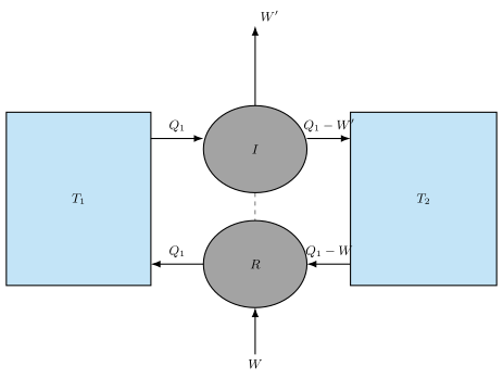
Imagine a reversible Carnot engine and an irreversible engine operating between the same hot reservoir (source at ) and cold reservoir (sink at ). Let act as a heat engine and act as a refrigerator. The arrangement is shown in Fig. 11.10.
- Engine absorbs heat from the source, does work , and rejects heat to the sink.
- Refrigerator takes heat from the sink, requires work to be done on it, and returns heat to the source.
Now, suppose for contradiction that the irreversible engine is more efficient than the reversible engine . That is, . For the same heat input , this means .
Consider the combined system of and as a single device. What is the net effect after one cycle?
- Net heat extracted from the cold sink: The sink gives to and receives from . The net heat taken from the sink is .
- Net heat delivered to the hot source: The source gives to and receives from . The net heat delivered to the source is zero.
- Net work output: The combined system does work (from ) and has work done on it (by ). The net work output is . …
Drawn by us to help you understand the concept clearly, and verified to make sure it's accurate. For exams, practice from your textbook's own diagram.
The P–V diagram in Fig. 11.9 is the centrepiece of the Carnot cycle. It plots pressure on the vertical axis against volume on the horizontal axis. Four labelled state points — at the top-left, to the right, at the bottom-right, and at the bottom-left — are connected by four smooth curves that form a closed, clockwise loop. The arrows on the curves show the direction of the cycle.
The two temperatures and are the key: is the temperature of the hot reservoir (the source), and is the temperature of the cold reservoir (the sink), with . The cycle consists of four reversible processes:
- Isothermal expansion at from to . The gas absorbs heat from the hot reservoir. On the diagram this is the top curve, a hyperbola (since for an ideal gas at fixed temperature).
- Adiabatic expansion from to . No heat exchange — the gas does work and cools to . This is the steeper curve dropping from right to bottom-right.
- Isothermal compression at from to . The gas rejects heat to the cold reservoir. This is the bottom curve, another hyperbola but at the lower temperature.
- Adiabatic compression from back to . No heat exchange — work is done on the gas, raising its temperature back to . This is the steeper curve rising from bottom-left to top-left.
The area enclosed by the loop represents the net work done by the engine in one cycle. Because the cycle is clockwise, the net work is positive (work done by the system).
The Carnot cycle is the most efficient possible heat engine operating between two fixed temperatures. Its efficiency depends only on and , not on the working substance.
The textbook develops the central result from this figure: the efficiency of a Carnot engine. For an ideal gas, the efficiency is
Here:
- is the efficiency (fraction of input heat converted to work).
- is the heat absorbed from the hot reservoir at temperature .
- is the heat rejected to the cold reservoir at temperature .
- and are absolute temperatures (in Kelvin).
The derivation uses the fact that for the two adiabatic processes, is constant, and for the two isothermal processes, is constant. Combining these relations for the four steps yields , leading directly to the efficiency formula above. …
Drawn by us to help you understand the concept clearly, and verified to make sure it's accurate. For exams, practice from your textbook's own diagram.
The figure shows a thought experiment that proves the Carnot engine is the most efficient possible engine operating between two fixed temperatures. It is a schematic block diagram, not a graph.
On the left is the hot reservoir at temperature . On the right is the cold reservoir at temperature . Between them, two devices are drawn. The top device is an irreversible engine (labelled I). It takes heat from the hot reservoir, does work , and rejects heat to the cold reservoir. The bottom device is a reversible refrigerator (labelled R). It takes heat from the cold reservoir, receives work from the engine, and delivers heat to the hot reservoir.
The key point is that the engine and refrigerator are coupled: the work output of the irreversible engine drives the reversible refrigerator, which requires work to run. The figure is drawn for the case .
The diagram does not show a Carnot engine. It shows an irreversible engine (any real engine) coupled to a reversible refrigerator (an ideal Carnot refrigerator). The purpose is to compare their performances.
The physical idea is a proof by contradiction. If the irreversible engine were more efficient than a Carnot engine, then . The net result of the combined system would be:
- The hot reservoir receives a net heat .
- The cold reservoir loses a net heat .
- The net work done on the surroundings is .
But the crucial observation is that the hot reservoir ends up with more heat than it started with (because for an efficient irreversible engine), and the cold reservoir ends up with less heat. The net effect is that heat has been extracted from the cold reservoir and converted entirely into work, with no other change. This violates the Kelvin-Planck statement of the Second Law of Thermodynamics, which forbids a cyclic process that converts heat completely into work without any other effect.
The contradiction forces the conclusion that no irreversible engine can be more efficient than a reversible (Carnot) engine operating between the same two temperatures. This is the Carnot theorem. …