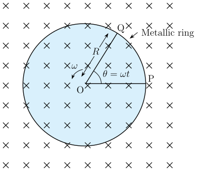
Q.A metallic rod of 1 m length is rotated with a frequency of 50 rev/s, with one end hinged at the centre and the other end at the circumference of a circular metallic ring of radius 1 m, about an axis passing through the centre and perpendicular to the plane of the ring (Fig. 6.11).
Concept understanding — Motional Emf
Motional Emf
When a conductor moves through a magnetic field, the free charges inside it experience a magnetic force. This force pushes the charges along the conductor, setting up a potential difference across its ends — a motional emf. It is electromagnetic induction viewed from a moving conductor rather than from a changing field.
Origin: the Lorentz force
Consider a straight rod of length l moving with velocity v perpendicular to a uniform field B. Each free charge q feels a force
F=q(v×B)
of magnitude qvB directed along the rod. Charges pile up at the ends until the electric field they create balances the magnetic force. The resulting potential difference — the motional emf — is
ε=Bvl
Consistency with Faraday's law
Let the rod of length l slide along parallel conducting rails, sweeping out a distance x. The enclosed area is A=lx, so the flux is Φ=Blx. Then
ε=−dtdΦ=−Bldtdx=−Blv
The magnitude Bvl matches the Lorentz-force result, showing that the flux rule and the force picture agree.
Worked example
A rod of length 0.4m moves at 5m/s perpendicular to a field of 0.5T:
ε=Bvl=0.5×5×0.4=1V
If the circuit resistance is 2Ω, the induced current is I=ε/R=0.5A.
Force and energy
Once current I flows, the field exerts a retarding force F=BIl on the rod, opposing its motion (Lenz's law). To keep the rod moving at constant speed, an external agent must supply power
P=Fv=BIlv=εI
exactly equal to the electrical power dissipated in the circuit — energy is conserved.
Motional emf arises only from the component of velocity perpendicular to B. Motion parallel to the field produces no emf.
Motional emf, derived from the Lorentz force on charges in a moving conductor, is a key numerical topic within the NCERT Class 12 Physics chapter on electromagnetic induction, tested in CBSE boards and JEE Main. Searches for "motional emf formula and derivation class 12 physics" will find this rod-on-rails explanation, consistent with Faraday's flux rule, matches the NCERT-prescribed derivation.
Why this formula?
Motional EMF: Why the Formula Holds
Let's build this from first principles — understanding the why before the formula.
The Core Idea
Motional EMF arises when a conductor moves through a magnetic field. The key insight: moving charges in a magnetic field experience a magnetic force, which acts like a battery pushing charges around the conductor.
Step 1: The Force on a Moving Charge
A charge q moving with velocity v in a magnetic field B feels the Lorentz magnetic force:
Fm=q(v×B)
This force is perpendicular to both velocity and magnetic field.
Step 2: What Happens Inside a Moving Conductor
Consider a straight metal rod of length L moving with constant velocity v perpendicular to a uniform magnetic field B (pointing into the page).
- Free electrons in the rod are moving with the rod at velocity v.
- Each electron experiences a magnetic force:
Fm=−e(v×B)
(negative sign because electron charge is −e)
- This force pushes electrons along the rod — say, toward one end.
Step 3: Charge Separation Creates an Electric Field
As electrons accumulate at one end, that end becomes negatively charged, leaving the other end positively charged.
- This charge separation creates an internal electric field E inside the rod, pointing from positive to negative end.
- The electric field exerts an opposing force on the electrons:
Fe=−eE
Step 4: Equilibrium — The "Battery" is Formed
Charge keeps moving until the electric force balances the magnetic force:
Fe+Fm=0
−eE−e(v×B)=0
E=−(v×B)
Magnitude-wise (for perpendicular v and B):
E=vB
Step 5: From Electric Field to EMF
The motional EMF E is the work done per unit charge to move a test charge from one end to the other:
E=∫negativepositiveE⋅dl
For a uniform field along the rod of length L:
E=E⋅L=vBL
The Key Formula
Motional EMF for a straight conductor moving perpendicular to B:
E=BLv
Why This Makes Physical Sense
| Quantity | Role |
|---|---|
| B | Stronger magnetic field → larger force on charges |
| L | Longer conductor → more charge separation possible |
| v | Faster motion → larger magnetic force → larger EMF |
Alternative Derivation: Faraday's Law
The same result comes from Faraday's law of induction:
E=−dtdΦB
For a rod of length L moving with speed v through a field B, the area swept per second is Lv, so:
dtdΦB=B⋅dtdA=BLv
Thus:
E=BLv
Both approaches give the same answer — confirming consistency.
Important Exam Points
- Direction: Use Fleming's right-hand rule (generator rule) to find polarity.
- General formula (when v and B are not perpendicular):
E=BLvsinθ
where θ is the angle between v and B.
- EMF is induced only while the conductor moves — stop the motion, stop the EMF.
Bottom line: Motional EMF is simply the magnetic force acting on moving charges inside a conductor, creating a charge separation that acts like a battery. The formula E=BLv is a direct consequence of balancing magnetic and electric forces.
The key idea is motional emf in a rotating rod: each segment of the rod cuts magnetic field lines at a different speed, so the emf is found by integrating dE=Bvdr along the rod.
- The rod rotates with angular velocity ω=2πf=2π×50=100π rad/s.
- At a distance r from the centre, the linear speed is v=ωr. The motional emf across a small element dr is dE=Bvdr=Bωrdr.
- Integrate from r=0 to r=R=1 m:
E=∫0RBωrdr=Bω2R2.
- Substitute values: B=1 T, ω=100π rad/s, R=1 m:
E=1×100π×212=50π V.
The emf between the centre and the metallic ring is 50π V.
A rod rotating in a field develops a motional emf ε=21Bωℓ2. With B=1 T, ℓ=1 m, and ω=2π(50)=100π rad s−1: ε=21(1)(100π)(1)2=50π≈157 V.
Step-by-Step Solution
Take a small element at distance x from the hinge; it moves with speed v=ωx. The motional emf across the whole rod is
ε=∫0ℓBvdx=∫0ℓBωxdx=21Bωℓ2.
Angular frequency:
ω=2πf=2π×50=100π rad s−1≈314.2 rad s−1.
Therefore:
ε=21×1×(100π)×(1)2=50π≈157 V.
The emf between the centre and the ring is ε=50π V≈157 V.
Method: Motional EMF in a Rotating Rod (Faraday's Law in Rotating Frame)
This is a classic problem of a rotating conductor in a uniform magnetic field. The key insight: different parts of the rod move at different speeds, so we cannot simply use Blv with a single v.
Steps
-
Identify the geometry
- Rod length: L=1 m
- Rotation frequency: f=50 rev/s
- Magnetic field: B=1 T, uniform and parallel to axis
- One end at centre (hinged), other end slides on ring
-
Consider a small element
Take a small segment of the rod at distance r from the centre, of length dr.
Its linear velocity: v=ωr, where ω=2πf=100π rad/s
-
EMF across the small element
The motional emf across this segment:
dE=Bvdr=Bωrdr
- Integrate over the entire rod The total emf between centre (r=0) and ring (r=L):
E=∫0LBωrdr=Bω[2r2]0L=21BωL2
- Substitute values
E=21×1×(100π)×(1)2=50π V
Final Answer
E=50π V≈157 V
Why this works: Each radial segment of the rod cuts magnetic field lines at a speed proportional to its distance from the centre. The integration accounts for this varying speed, giving the correct net emf.
Common Mistakes in Motional EMF (Rotating Rod Problem)
Mistake 1: Using v at the free end only
The error: Students often calculate emf as E=Blv, taking v as the velocity of the free end (v=ωR). This gives:
E=(1)(1)(2π×50×1)=100π V
Why it's wrong: Different points on the rod move at different speeds. The free end moves fastest (v=ωR), while the hinged end is stationary (v=0). Using only the maximum velocity overestimates the emf.
How to avoid: Remember that for a rotating rod, each infinitesimal segment dr at distance r from the centre moves with velocity v=ωr. The emf contributed by each segment is dE=B⋅v⋅dr=Bωrdr. Integrate from r=0 to r=R:
E=∫0RBωrdr=21BωR2
Mistake 2: Forgetting to convert frequency to angular velocity
The error: Students directly substitute f=50 into formulas without converting to ω.
Why it's wrong: The formula v=ωr requires angular velocity in rad/s, not rev/s.
How to avoid: Always convert: ω=2πf=2π×50=100π rad/s. Then use:
E=21B(2πf)R2=21×1×100π×12=50π V
Mistake 3: Confusing the rod with the ring
The error: Students try to find emf induced in the ring instead of the rod.
Why it's wrong: The ring is stationary and lies in a plane perpendicular to the magnetic field. A stationary loop in a uniform, constant field has zero induced emf (no change in flux).
How to avoid: Identify the moving conductor — it's the rod. The ring only serves as a sliding contact to complete the circuit. The emf is generated only in the rod as it cuts magnetic field lines.
Mistake 4: Forgetting the direction of emf (polarity)
The error: Students calculate magnitude but don't identify which end (centre or ring) is at higher potential.
Why it's wrong: Exam questions often ask for "emf between centre and ring" — this implies both magnitude and polarity.
How to avoid: Use Fleming's Right Hand Rule:
- Thumb: direction of motion of the rod (tangential)
- Forefinger: magnetic field direction (into/out of page)
- Middle finger: direction of induced current (and hence emf)
For this setup, the centre is at lower potential and the ring at higher potential (or vice versa depending on field direction — check carefully).
Mistake 5: Using wrong formula for average velocity
The error: Students take average velocity as 20+ωR=2ωR and then use E=Blvavg.
Why it's wrong: While this gives the correct numerical answer (21BωR2), it's conceptually sloppy and fails if the rod isn't straight or the field isn't uniform.
How to avoid: Always use the integration method — it's rigorous and works for all cases. The average velocity trick only works here by coincidence (linear variation of v with r).
Quick Summary Checklist
| Mistake | Fix |
|---|---|
| Using v at free end only | Integrate dE=Bωrdr |
| Forgetting ω=2πf | Always convert frequency |
| Inducing emf in the ring | Emf is only in the rod |
| Missing polarity | Use Fleming's Right Hand Rule |
| Blindly using average velocity | Use integration method |
Final correct answer: 50π V (approximately 157 V)
🎓Unlock everything free for 14 days
- ✓Full step-by-step solutions
- ✓Concept-first explanations
- ✓Methods, shortcuts & mistakes
- ✓PYQ mapping + timed mock tests
Full access for 14 days. No credit card required.