Physics · Ch 7 — Alternating Current
Resonance
Resonance
What is Resonance?
Resonance is a phenomenon that occurs in any system that has a natural frequency — the frequency at which it prefers to oscillate. When such a system is driven by an external source at a frequency close to its natural frequency, the amplitude of oscillation becomes very large.
- Example: A child on a swing. The swing has a natural frequency. If the child pulls the rope at the same frequency as the swing's natural frequency, the swing goes higher and higher.
In a series RLC circuit, the current amplitude depends on the driving frequency . The circuit has a natural frequency at which the inductive and capacitive effects cancel each other out. This is the resonant frequency.
The Condition for Resonance
In a series RLC circuit, the impedance is given by:
where:
- is the inductive reactance.
- is the capacitive reactance.
The current amplitude is:
At a particular frequency , the inductive and capacitive reactances become equal:
This is the condition for resonance. When this happens:
- The impedance is minimum: .
- The current amplitude is maximum: .
The Resonant Frequency
Setting gives:
Solving for :
This is the resonant angular frequency. The corresponding resonant frequency (in Hz) is:
Key Observations from the Textbook
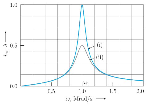
- Figure 7.14 shows how varies with for a circuit with , , and .
- For , the peak current is .
- For , the peak current is .
- The resonant frequency is .
- The current amplitude at resonance is inversely proportional to . A smaller gives a sharper, higher peak.
Why Resonance is Important: Tuning
Resonant circuits are used in tuning (e.g., in radios and TVs).
- The antenna picks up signals from many stations at different frequencies.
- The tuning circuit (a series RLC circuit) is driven by these signals.
- By varying the capacitance (or inductance ), we change the resonant frequency of the circuit.
- When matches the frequency of a desired station, the current amplitude for that signal becomes maximum. …
Drawn by us to help you understand the concept clearly, and verified to make sure it's accurate. For exams, practice from your NCERT textbook's own diagram.
The figure is a resonance curve for a series RLC circuit. It plots the current amplitude (in amperes) on the vertical axis against the angular frequency (in Mrad/s) on the horizontal axis.
- Horizontal axis (): Marked from 0.5 to 2.0 Mrad/s. The resonant frequency Mrad/s is clearly indicated.
- Vertical axis (): Ranges from 0.0 to 1.0 A.
- Two curves:
- Curve (i) (): A tall, narrow peak reaching A at .
- Curve (ii) (): A shorter, broader peak reaching A at the same .
- Both curves fall symmetrically to near zero away from , showing that current is maximum only at resonance.
Physical idea: The circuit exhibits resonance when the inductive reactance equals the capacitive reactance . At this frequency, the impedance is minimum (), so the current amplitude is maximum. A smaller gives a sharper, higher peak; a larger gives a broader, lower peak.
Key formula: The current amplitude is
where , , and is the source voltage amplitude. At resonance,
…