Physics · Ch 1 — Electric Charges and Fields
Electric Field Due to a System of Charges
Electric Field Due to a System of Charges
Concept First
The electric field due to a single point charge is defined as the force per unit positive test charge. For a system of multiple point charges, the same definition holds: the electric field at a point is still the force experienced by a unit positive test charge placed there, provided the test charge is small enough that it does not disturb the original positions of the source charges.
The key tool to find this net field is the superposition principle: the total electric field at any point is the vector sum of the fields produced by each individual charge, as if the others were absent.
Derivation and Explanation
Consider point charges located at positions relative to an origin . We want the electric field at a point with position vector .
Step 1: Field due to a single charge
For a charge at , the electric field at is given by Coulomb's law:
where:
- is the distance between and point .
- is a unit vector pointing from to .
Step 2: Superposition principle
The total electric field at is the vector sum of all such individual fields:
…
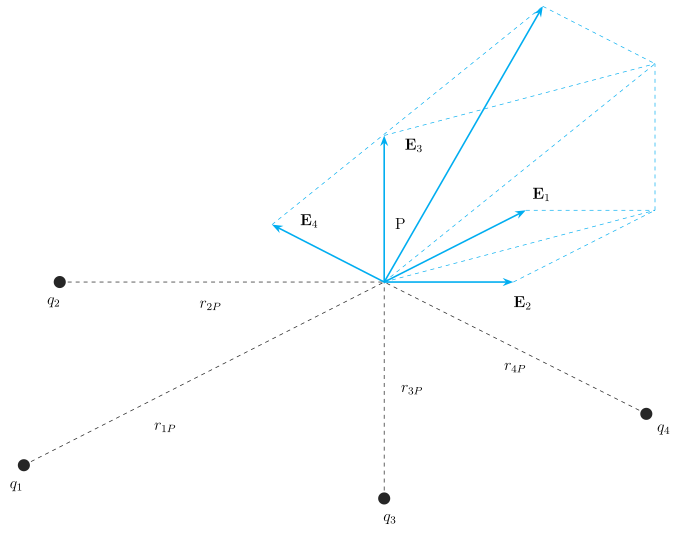
Drawn by us to help you understand the concept clearly, and verified to make sure it's accurate. For exams, practice from your NCERT textbook's own diagram.
The figure illustrates the superposition principle for electric fields. At the field point P, four source charges (, , , ) are positioned around it. Each charge is connected to P by a dashed line labelled , , , — these are the distances from each source charge to P.
From P, four vectors , , , are drawn, each pointing away from its source charge if the charge is positive (or toward it if negative, though the figure does not specify signs). These vectors represent the individual electric fields at P due to each charge alone. A dashed head-to-tail construction is shown: the tail of starts at the head of , the tail of at the head of , and so on. The resultant (unlabelled) vector is the straight arrow from the tail of to the head of , pointing up and to the right — this is the net electric field at P.
Physical idea: The total electric field at a point due to multiple charges is the vector sum of the fields from each individual charge. The head-to-tail construction is a geometric way to perform this vector addition.
Key formula developed with this figure is the superposition expression:
where:
- is the net electric field at point P (position vector )
- is the -th source charge
- is the distance from to P …