Physics · Ch 14 — Semiconductor Electronics: Materials, Devices and Simple Circuits
p-n Junction Diode under Forward Bias
p-n Junction Diode under Forward Bias
Forward Bias: The Basic Idea
When we connect a battery to a p-n junction diode so that the p-side is at a higher potential than the n-side, we say the diode is forward biased. Specifically, the positive terminal of the battery is connected to the p-side, and the negative terminal to the n-side.
The applied voltage does not drop uniformly across the entire diode. The p-side and n-side regions have plenty of free charge carriers, so their resistance is very low. The depletion region, on the other hand, is almost devoid of mobile charges — it behaves like an insulator with very high resistance. Consequently, almost the entire applied voltage drops across the depletion region itself. The voltage drop across the neutral p-side and n-side is negligible.
This is a crucial simplification. It means we can treat the barrier height as being directly modified by the full applied voltage , without worrying about voltage division along the rest of the diode.
Effect on the Depletion Region and Barrier Height
The direction of the applied voltage is opposite to the direction of the built-in potential . The built-in potential tries to push holes back into the p-side and electrons back into the n-side. The forward bias pushes holes towards the junction from the p-side and electrons towards the junction from the n-side.
This has two immediate consequences:
- Depletion layer width decreases. The external field pushes majority carriers (holes from p-side, electrons from n-side) into the depletion region, where they neutralise some of the fixed ions. The space-charge region shrinks.
- Barrier height is reduced. The effective potential barrier that carriers must overcome to cross the junction is no longer . It becomes:
Current Flow Under Forward Bias
The reduction in barrier height is the key to current flow. Here is how the current builds up as the applied voltage increases.
For small applied voltages: The barrier is only slightly lowered. Only those carriers that happen to possess kinetic energy greater than the reduced barrier can surmount it. These are the carriers in the uppermost energy levels of their respective bands. Their number is small, so the resulting current is small.
For larger applied voltages: The barrier height is significantly reduced. A much larger fraction of the majority carriers now has enough energy to cross the junction. The current therefore increases substantially.
Do not confuse this with the idea that the barrier disappears entirely. Even under forward bias, a reduced barrier still exists. Current flows because a sufficient number of carriers have enough energy to overcome it, not because the barrier is gone.
Minority Carrier Injection
Once carriers cross the junction, they become minority carriers on the other side.
- Electrons from the n-side (majority carriers) cross the depletion region and enter the p-side. In the p-side, electrons are minority carriers.
- Holes from the p-side (majority carriers) cross the junction and enter the n-side. In the n-side, holes are minority carriers.
This process is called minority carrier injection. The forward bias literally "injects" a large number of minority carriers into each region.
Concentration Gradient and Diffusion Current
At the junction boundary, the concentration of injected minority carriers is very high. Far away from the junction, deep inside the p-side or n-side, the concentration of these minority carriers is very low (their equilibrium value). This creates a steep concentration gradient.
Because of this gradient, the injected carriers diffuse away from the junction:
- Injected electrons on the p-side diffuse from the junction edge of the p-side towards the far end (the ohmic contact) of the p-side.
- Injected holes on the n-side diffuse from the junction edge of the n-side towards the far end of the n-side. …
Drawn by us to help you understand the concept clearly, and verified to make sure it's accurate. For exams, practice from your NCERT textbook's own diagram.
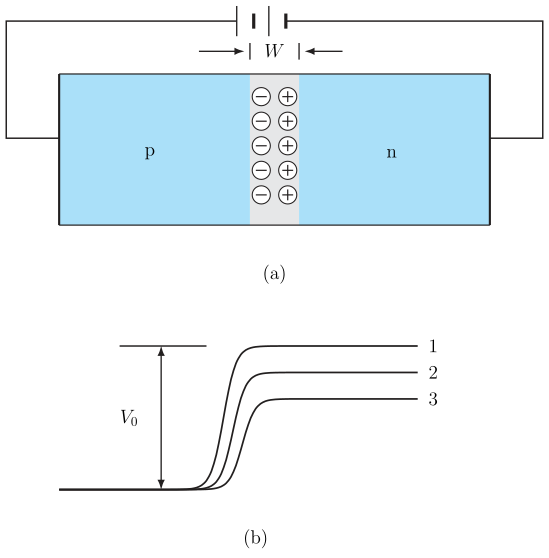
The figure has two parts. Panel (a) shows the physical circuit: a p-n junction diode with the p-region on the left and the n-region on the right. A battery is connected so that its positive terminal goes to the p-side and its negative terminal to the n-side — this is the forward bias arrangement. The depletion region at the junction is drawn noticeably narrow, which is the key visual cue: forward bias shrinks the depletion layer.
Panel (b) is a graph of electric potential (vertical axis) against position (horizontal axis) across the diode. Three curves are plotted, labelled 1, 2, and 3. Curve 1 corresponds to the equilibrium case (no battery, ): the potential jumps by the built-in barrier height across the depletion region. Curve 2 shows what happens when a small forward voltage is applied — the barrier height drops to , but only slightly below . Curve 3 is for a larger forward voltage: the barrier is reduced further, again to , but now the reduction is substantial. The horizontal axis is marked with "p" on the left and "n" on the right, so the potential is higher on the n-side than on the p-side in equilibrium, and the applied voltage opposes this built-in difference.
The potential plot is not a graph of voltage versus current; it is a spatial profile of electric potential energy per unit charge across the diode. The vertical drop across the depletion region is the barrier that charge carriers must overcome.
The physical idea is straightforward. In forward bias, the external battery pushes electrons from the n-side toward the junction and holes from the p-side toward the junction. Because the applied voltage opposes the built-in potential , the net barrier that carriers face becomes . A smaller barrier means more carriers have enough thermal energy to cross the junction. The depletion width shrinks because the electric field that originally held the fixed ions apart is weakened by the external field.
The textbook's own treatment of this figure stays qualitative: a smaller barrier means more carriers have enough thermal energy to cross the junction, so forward current rises steeply as the applied voltage increases and the barrier keeps shrinking. (The exponential diode current-voltage equation and the diffusion-based derivation of the reverse saturation current are not part of the current rationalized NCERT syllabus for this chapter and are not shown here.)
A common mistake is to think the applied voltage adds to the built-in potential. It does not. The applied voltage opposes , so the net barrier is , not . Forward bias reduces the barrier; reverse bias increases it. …
Drawn by us to help you understand the concept clearly, and verified to make sure it's accurate. For exams, practice from your NCERT textbook's own diagram.
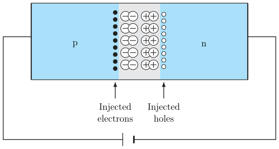
Fig. 14.14 is a single schematic panel (NOT a two-part diagram with a separate concentration-vs-distance graph -- the real printed figure has no such second panel). It shows a cross-section of a p-n junction bar under forward bias, with the p-region on the left and the n-region on the right, and the depletion/junction region drawn as a band containing a mix of small circled + and - symbols in the middle.
Two upward-pointing arrows lead out of that band: one labelled "Injected electrons," the other labelled "Injected holes." These arrows show the two things that happen at the same time once forward bias is applied and the barrier is lowered: electrons cross from the n-side into the p-side (where they become minority carriers), and holes cross from the p-side into the n-side (where they also become minority carriers). A battery symbol below the bar completes the forward-bias circuit, matching the same battery-polarity convention as Fig. 14.13(a).
The physical idea is this: under forward bias, the barrier height is reduced from to (as shown in Fig. 14.13(b)). This allows a significant number of majority carriers to cross the junction. Once across, they become minority carriers on the other side -- electrons are minority carriers in the p-region, holes are minority carriers in the n-region. These injected carriers then diffuse away from the junction into the bulk of the region they've entered, and this diffusion of injected minority carriers is what constitutes the diode's forward current.
The total forward current is the sum of two contributions: the diffusion current of electrons injected into the p-side, and the diffusion current of holes injected into the n-side. Both currents flow in the same direction (from n to p inside the diode), so they add together. …