Physics · Ch 10 — Alternating Current
Transformers
Transformers
Why Do We Need Transformers?
In the transmission and use of electrical power, we often need to change an alternating voltage to a higher or lower value. For example, power stations generate electricity at a moderate voltage, but to transmit it over long distances with minimal loss, the voltage is stepped up (increased). At your home, it is stepped down (decreased) to a safe 240 V. The device that does this is the transformer.
Principle and Construction
A transformer works on the principle of mutual induction: a changing current in one coil induces an emf in a nearby coil.
- Core: A soft-iron core is used. It is laminated (made of thin sheets) to reduce energy losses.
- Coils: Two sets of insulated coils are wound on this core.
- Primary coil: The input coil, with turns.
- Secondary coil: The output coil, with turns.
The coils can be wound one on top of the other or on separate limbs of the core.
How It Works: The Ideal Transformer
We first consider an ideal transformer with these assumptions:
- Primary winding has negligible resistance.
- No flux leakage — the same magnetic flux links every turn of both the primary and secondary coils.
- No energy losses (100% efficiency).
When an alternating voltage is applied to the primary, an alternating current flows. This produces an alternating magnetic flux in the core.
- Induced emf in the secondary (): The changing flux induces an emf in the secondary coil. By Faraday's law:
If the secondary is open (or draws very little current), the voltage across it $v_s$ is approximately equal to this induced emf: $v_s \approx \varepsilon_s$. So,
- Back emf in the primary (): The changing flux also induces a back emf in the primary coil itself.
Because the primary has zero resistance (assumption 1), the applied voltage $v_p$ must exactly balance this back emf to prevent an infinite current. Thus, $v_p = \varepsilon_p$.
The Voltage Transformation Ratio
From the two equations above, we can relate the primary and secondary voltages. Dividing by :
This is the fundamental transformer equation for an ideal transformer:
- and are the rms (or peak) voltages across the secondary and primary.
- and are the number of turns in the secondary and primary.
The Current Transformation Ratio
For an ideal transformer, power input equals power output (100% efficiency).
Combining this with the voltage ratio:
So, the current ratio is the inverse of the turns ratio:
- and are the rms (or peak) currents in the secondary and primary.
Step-Up and Step-Down Transformers
-
Step-Up Transformer:
- Voltage is increased:
- Current is decreased:
- Example: A transformer with and () steps up a 220 V, 10 A input to 440 V, 5.0 A.
-
Step-Down Transformer:
- Voltage is decreased:
- Current is increased:
Energy Losses in Real Transformers
Real transformers are not 100% efficient. Energy is lost due to: …
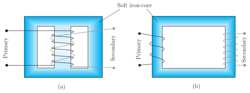
Drawn by us to help you understand the concept clearly, and verified to make sure it's accurate. For exams, practice from your textbook's own diagram.
Figure 7.16 shows two different ways to wind the primary and secondary coils of a transformer on a soft-iron core. In both arrangements, the core is drawn as a hollow rectangular loop (like a picture frame), and the coils are represented as helical textures with terminal dots.
-
Panel (a) – Concentric winding: The primary and secondary coils are wound one on top of the other on the central limb of the core. The primary leads emerge from the left side, and the secondary leads from the right side. This arrangement ensures that almost all the magnetic flux produced by the primary links the secondary, minimising flux leakage.
-
Panel (b) – Separate-limb winding: The primary coil is wound on the left limb of the core, and the secondary coil on the right limb. The leads are brought out on their respective sides. Here, the flux path is longer and some flux may escape, leading to greater flux leakage compared to panel (a).
The core itself is labelled "Soft iron-core" with a leader pointing to the top centre of the shaded rectangular core. The soft-iron material is chosen because it has high magnetic permeability and low hysteresis loss, making it efficient for guiding the alternating magnetic flux.
Physical idea taught by the figure
The figure illustrates the core principle of a transformer: two coils are magnetically coupled via a common soft-iron core. When an alternating voltage is applied to the primary coil, it produces an alternating magnetic flux in the core. This flux links the secondary coil and induces an alternating emf in it. The two winding arrangements show practical ways to achieve this coupling — the concentric design (a) is more efficient because it reduces flux leakage, while the separate-limb design (b) is simpler to construct but less efficient.
Key formulas developed with this figure
From the textbook, the induced emfs in the primary and secondary coils are:
where:
- = number of turns in the primary coil,
- = number of turns in the secondary coil,
- = magnetic flux through each turn of the core (assumed same for both coils in an ideal transformer).
Since the primary voltage equals the back emf (for an ideal transformer with negligible primary resistance), and the secondary voltage equals (when secondary current is small), we obtain the voltage transformation ratio:
For a 100% efficient (ideal) transformer, power input equals power output:
…