Q.A pair of adjacent coils has a mutual inductance of 1.5 H. If the current in one coil changes from 0 to 20 A in 0.5 s, what is the change of flux linkage with the other coil?
🔒You're viewing a preview — the full solution, concept, methods & PYQ mapping are locked.
🔒 Start your 14-day free trial to unlock the full solution →Concept understanding — Mutual Inductance
Mutual Inductance: From Intuition to Definition
Imagine you have two separate coils of wire placed near each other. You connect one coil to a battery — current starts flowing through it. Now, something strange happens in the other coil, which isn't connected to anything: a voltage appears across its ends. That voltage can even light a small bulb for an instant.
This is mutual inductance in action. One circuit "feels" the changing current in another circuit, even though they are not physically connected.
The Core Intuition
The key idea is changing magnetic fields. When current flows through a coil, it creates a magnetic field around it. If that current changes (increases or decreases), the magnetic field also changes. This changing field reaches the second coil. And a changing magnetic field, by Faraday's law, induces an electromotive force (emf) in any nearby conductor.
So mutual inductance is simply: how effectively a change in current in one coil induces a voltage in another coil.
Mutual inductance only works when the current is changing. A steady DC current produces a steady magnetic field, which induces nothing in the second coil. That's why the bulb lights only for an instant when you first connect the battery — the current is rising from zero.
The Precise Definition
Let's formalise this. Consider two coils: coil 1 and coil 2. Let I1 be the current in coil 1. This current produces a magnetic flux Φ21 through coil 2 (the flux from coil 1 that passes through coil 2).
The mutual inductance M (also written M21) is defined as the constant of proportionality between the current I1 and the flux it produces in coil 2:
Φ21=MI1
Similarly, if current I2 flows in coil 2, it produces a flux Φ12 through coil 1:
Φ12=MI2
The mutual inductance M is the same for both directions. M21=M12=M. This is a fundamental symmetry property.
Now, by Faraday's law, the induced emf in coil 2 due to a changing current in coil 1 is:
E2=−dtdΦ21=−MdtdI1
And the induced emf in coil 1 due to a changing current in coil 2 is:
E1=−MdtdI2
The negative sign is Lenz's law — the induced emf opposes the change that produced it.
Units
The SI unit of mutual inductance is the henry (H), named after Joseph Henry. From the definition:
1H=1AV⋅s=1AWb
One henry means that a current change of 1 ampere per second induces an emf of 1 volt in the other coil.
What Determines Mutual Inductance?
M depends on:
- Geometry: size, shape, number of turns of both coils
- Relative position: how close they are and how they are oriented
- Core material: if a magnetic material (like iron) is present, M increases dramatically
For two coaxial solenoids of length l, with N1 and N2 turns, and cross-sectional area A, the mutual inductance is: …
Why this formula?
Mutual Inductance: Why the Formula Holds
Mutual inductance is a beautiful example of Faraday's Law in action — it describes how a changing current in one coil can induce an EMF in a nearby coil, without any direct electrical connection.
1. The Core Idea: Flux Linkage
Imagine two coils, Coil 1 and Coil 2, placed close together.
- When a current I1 flows in Coil 1, it creates a magnetic field B1.
- Some of the magnetic field lines from Coil 1 pass through Coil 2.
- The total magnetic flux through Coil 2 due to I1 is called the mutual flux:
Φ21=flux through Coil 2 due to current in Coil 1
Key insight: For a fixed geometry (coils not moving), the mutual flux is directly proportional to the current I1:
Φ21∝I1
Why? Because B1 itself is proportional to I1 (Biot–Savart law), and the area of Coil 2 is fixed. So:
Φ21=M21I1
where M21 is the mutual inductance (a constant depending on coil shapes, sizes, turns, and relative positions).
2. Why the EMF Formula Arises
Now, if I1 changes with time, then Φ21 changes with time. By Faraday's Law, a changing flux induces an EMF in Coil 2:
E2=−dtdΦ21
Substitute Φ21=M21I1:
E2=−M21dtdI1
That's the key formula. The negative sign (Lenz's law) tells us the induced EMF opposes the change in flux.
3. Symmetry: M12=M21
If we reverse the situation — current I2 in Coil 2 induces flux Φ12 in Coil 1 — we get:
Φ12=M12I2
and
E1=−M12dtdI2
A deep result from energy conservation (or from the reciprocity theorem in electromagnetism) shows:
M12=M21=M
So we simply call it M, the mutual inductance between the two coils.
4. The Complete Formula Set
| Quantity | Expression | Why? |
|---|---|---|
| Mutual flux (Coil 2 due to Coil 1) | Φ21=MI1 | Proportionality from Biot–Savart |
| Induced EMF in Coil 2 | E2=−MdtdI1 | Faraday's Law |
| Mutual flux (Coil 1 due to Coil 2) | Φ12=MI2 | Symmetry |
| Induced EMF in Coil 1 | E1=−MdtdI2 | Faraday's Law |
5. Physical Intuition (Exam-Ready) …
The key idea is Mutual Inductance: the flux linkage in one coil due to current in another is Φ2=MI1, so a change in current causes a proportional change in flux linkage.
Step 1: Write the relation for flux linkage.
For coil 2 due to current I1 in coil 1:
Φ2=MI1.
Step 2: The change in flux linkage is
ΔΦ2=MΔI1.
Step 3: Substitute values: …
The change in flux linkage with the second coil is found directly from the definition of mutual inductance: ΔΦ=MΔI. Here, ΔΦ=1.5×20=30 Wb-turns.
Mutual inductance is a measure of how effectively a changing current in one coil induces a magnetic flux through another coil. The key idea is that the flux linkage in the second coil is proportional to the current in the first coil, with the constant of proportionality being the mutual inductance M.
The definition is:
If a current I1 flows in coil 1, the flux linkage (total magnetic flux linking all turns) in coil 2 is
Φ2=MI1
where Φ2 is in weber-turns (Wb-turns) and M is in henries (H). This is a direct, linear relationship — no time derivative involved yet.
When the current changes, the flux linkage changes by the same proportion. So the change in flux linkage ΔΦ2 is simply M times the change in current ΔI1:
ΔΦ2=MΔI1
This is the cleanest way to get the answer. The time interval (0.5 s) is irrelevant for the change in flux linkage — it only matters if you were asked for the induced emf (which would be MΔtΔI).
A common mistake is to bring the time into the flux calculation. The flux linkage change depends only on the net current change, not on how fast it happens. The time is a red herring here.
Now let’s plug in the numbers.
- Identify the given values Mutual inductance: M=1.5 H …
Method: Faraday's Law of Electromagnetic Induction (using Mutual Inductance)
This problem is solved using the definition of mutual inductance — which directly relates the induced flux linkage in one coil to the current change in the other coil.
Step-by-step solution
Step 1: Recall the defining equation for mutual inductance
The mutual inductance M between two coils is defined as:
M=ΔI1N2ΔΦ21
where:
- N2ΔΦ21 = flux linkage in coil 2 due to current in coil 1
- ΔI1 = change in current in coil 1
Step 2: Identify the given values
- Mutual inductance, M=1.5 H
- Change in current in the first coil, ΔI1=20 A−0 A=20 A
- Time taken, t=0.5 s (not needed for flux linkage — only needed if we wanted induced emf)
Step 3: Rearrange the formula to find flux linkage
From the definition:
N2ΔΦ21=M×ΔI1
Step 4: Substitute and calculate …
Here are the most common mistakes students make on this Mutual Inductance problem, and how to avoid each one.
Mistake 1: Confusing Flux Linkage with Induced EMF
- The Mistake: Students often calculate the induced EMF (E=−MdtdI) and then stop, thinking that is the answer. The question asks for the change in flux linkage (ΔΦ), not the voltage.
- Why it happens: The formula for induced EMF is very prominent, and the negative sign makes it look like the "main" result. Students forget that flux linkage is the cause of the EMF, not the EMF itself.
- How to Avoid:
- Read the question twice. Underline the exact quantity asked: "change of flux linkage."
- Recall the definition: Mutual inductance M is defined as the flux linkage in one coil per unit current in the other.
M=I1N2Φ21
Therefore, the **change** in flux linkage is directly:
Δ(N2Φ21)=M×ΔI1
- **Don't touch the EMF formula** unless the question specifically asks for induced voltage.
Mistake 2: Forgetting the "Change" (Δ)
- The Mistake: Students plug in the final current value (20 A) directly into the formula, ignoring the initial current (0 A). They calculate 1.5×20=30, missing the fact that it's a change.
- Why it happens: The problem gives a clear "from 0 to 20 A," but in the rush to solve, students treat the final value as the only value.
- How to Avoid:
- Always write the formula with Δ explicitly:
ΔΦ=M×ΔI
- **Calculate $\Delta I$ separately:**
ΔI=Ifinal−Iinitial=20−0=20 A
- **Check your work:** If the current started at 10 A and went to 20 A, would your answer change? If your method doesn't account for that, you're doing it wrong.
Mistake 3: Unnecessarily Involving Time (t)
- The Mistake: Students see "0.5 s" and immediately calculate the rate of change of current (dI/dt=20/0.5=40 A/s). They then multiply by M to get an EMF, and then try to convert that back to flux linkage, often making an error. …
Showing the 12 most recent of 28 on this concept.
- TG EAPCET 2026Set eng-2026-05-09-AN1 markMCQQ.When an inductor is connected to a 200 V dc supply, the current through it is 5 A and when the same inductor is connected to a 200 V ac supply of angular frequency 300 rads−1, the current through it is 4 A. The inductance of the inductor is (A) 100 mH (B) 200 mH (C) 50 mH (D) 75 mH
›Reveal solutionSolution
The dc case gives the coil’s resistance; the ac case gives its impedance; the difference yields the inductive reactance and hence the inductance. The answer is 100 mH.
The key idea is that an inductor is not a pure inductor in practice — it has some internal resistance due to the wire it’s wound from. When you connect it to a dc supply, only that resistance matters because the inductive reactance is zero for steady current. When you connect it to an ac supply, both the resistance and the inductive reactance oppose the current, so the impedance is larger and the current smaller. Comparing the two cases lets you isolate the inductance.
Let’s work it through.
- Find the resistance from the dc case. For a dc supply, the inductor behaves as a pure resistor R (the coil’s internal resistance). Ohm’s law gives
R=IdcVdc=5 A200 V=40 Ω.
- Find the impedance from the ac case. For the ac supply (rms values), the impedance Z of the series RL combination is
Z=IacVac=4 A200 V=50 Ω.
- Relate impedance to resistance and inductive reactance. For an RL series circuit,
Z=R2+XL2,where XL=ωL.
Substitute the known values:
50=402+(ωL)2.
- Solve for L. Square both sides: 2500=1600+(ωL)2⇒(ωL)2=900. …
- TG EAPCET 2026Set eng-2026-05-09-AN1 markMCQQ.If the length of a linear antenna is increased by 60% and the wavelength of the signal is decreased by 20%, then the percentage increase in the effective power radiated by the antenna is (A) 50 (B) 250 (C) 300 (D) 150
›Reveal solutionSolution
The effective power radiated by a linear antenna is proportional to (λL)2. Increasing L by 60% and decreasing λ by 20% multiplies λL by 2, so power increases by 300%. The answer is (C).
The key idea here is that for a linear antenna (like a half-wave dipole or a simple straight wire), the effective power radiated is not simply proportional to the length or the wavelength separately — it depends on the ratio of the antenna length to the wavelength. This comes from the fact that the radiation efficiency and the radiation resistance both scale with (L/λ)2 when the antenna is much shorter than the wavelength (a "short dipole" approximation). Even for a resonant antenna, the power radiated for a given current is proportional to the radiation resistance, which scales as (L/λ)2 for a short dipole. The problem implicitly uses this proportionality.
Let’s work through it step by step.
- Set up the proportionality. The effective power radiated P is proportional to (λL)2, where L is the antenna length and λ is the wavelength of the signal.
P∝(λL)2
- Express the changes. The length is increased by 60%, so the new length L′ is:
L′=L+0.60L=1.60L
The wavelength is decreased by 20%, so the new wavelength λ′ is:
λ′=λ−0.20λ=0.80λ
- Find the new ratio. The new ratio λ′L′ becomes:
λ′L′=0.80λ1.60L=0.801.60⋅λL=2⋅λL
So the ratio doubles.
- Find the new power. Since P∝(L/λ)2, the new power P′ is:
P′∝(2⋅λL)2=4(λL)2∝4P
That means P′=4P, i.e., the power becomes four times the original.
- Calculate the percentage increase. …
- TG EAPCET 2026Set eng-2026-05-10-FN1 markMCQQ.A circular coil of radius 10 cm is carrying a current. From the centre of the coil, the distance of a point on its axis where (dxdB) becomes maximum is (dxdB is the change in magnetic field with distance x from the centre of the coil) (A) 40 cm (B) 20 cm (C) 10 cm (D) 5 cm
›Reveal solutionSolution
The magnetic field on the axis of a circular coil varies with distance x, and its derivative dxdB is maximised where the second derivative of B vanishes. For a coil of radius R, this occurs at x=2R. With R=10 cm, the answer is 5 cm.
The magnetic field on the axis of a circular coil of radius R, carrying a current I, at a distance x from its centre is given by
B(x)=2(R2+x2)3/2μ0IR2.
This is a standard result derived from the Biot–Savart law — the field is symmetric about the centre and falls off as you move away. The question asks where the rate of change of this field, dxdB, is itself maximum. That means we are looking for the point where the slope of B(x) is steepest.
Why not just differentiate B and find where that derivative is largest? Because dxdB is itself a function of x, and its maximum occurs where its own derivative (the second derivative of B) is zero and changes sign. So the plan is:
- Write B(x).
- Compute dxdB.
- Differentiate again to get dx2d2B.
- Set dx2d2B=0 and solve for x.
Let’s do it step by step.
- Write B(x) and factor constants. Let k=2μ0IR2, a positive constant. Then
B(x)=k(R2+x2)−3/2.
- First derivative. Using the chain rule:
dxdB=k⋅(−23)(R2+x2)−5/2⋅2x=−3kx(R2+x2)−5/2.
The negative sign just tells us the field decreases as x increases — we care about the magnitude of the slope, but the location of the extremum of dxdB is the same whether we consider the signed derivative or its absolute value.
- Second derivative. Differentiate dxdB using the product rule. Let u=−3kx and v=(R2+x2)−5/2. Then
dx2d2B=u′v+uv′.
We have u′=−3k, and
v′=−25(R2+x2)−7/2⋅2x=−5x(R2+x2)−7/2.
So
dx2d2B=(−3k)(R2+x2)−5/2+(−3kx)[−5x(R2+x2)−7/2].
Simplify the second term: (−3kx)(−5x)=15kx2, so
dx2d2B=−3k(R2+x2)−5/2+15kx2(R2+x2)−7/2.
- Factor to set to zero. …
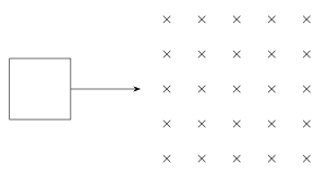
- TG EAPCET 2026Set eng-2026-05-10-FN1 markMCQQ.In the given figure, the directions of induced current in a square loop as it enters and leaves a uniform magnetic field respectively are (A) Counter clockwise, Clockwise (B) Clockwise, Counter clockwise (C) Counter clockwise, Counter clockwise (D) Clockwise, Clockwise
›Reveal solutionSolution
The key idea is Lenz’s law: induced current opposes the change in magnetic flux. As the loop enters the field, flux increases, so induced current creates opposing field (out of page) → counterclockwise. As it leaves, flux decreases, so induced current tries to sustain field (into page) → clockwise. Final answer: (A).
Concept & Intuition
This problem tests Lenz’s law, which tells us the direction of induced current: it always flows so that its own magnetic field opposes the change in the external magnetic flux through the loop.
Imagine the uniform magnetic field is directed into the page (a common convention). When the square loop moves into the field, more of its area is inside the field, so the flux (into page) increases. The induced current must create a field out of the page to oppose that increase. Using the right-hand rule, a counterclockwise current produces a field out of the page.
When the loop leaves the field, the flux (into page) decreases. Now the induced current tries to sustain the field into the page, so it must produce a field into the page — which requires a clockwise current.
Step-by-step reasoning
-
Identify the external field direction
The problem doesn’t explicitly state the field direction, but by standard convention in such diagrams, the uniform magnetic field is perpendicular to the plane of the loop and directed into the page (often shown by crosses). We adopt that.
-
Analyze the “entering” phase
- As the loop moves into the field, the area inside the field increases → magnetic flux (into page) increases.
- Lenz’s law: induced current opposes this increase → its own field must point out of the page.
- Right-hand rule: curl fingers in direction of current; thumb gives field direction. For field out of page, current must be counterclockwise.
- So first answer: counterclockwise.
-
Analyze the “leaving” phase
- As the loop moves out, the area inside the field decreases → flux (into page) decreases. …
-
- TG EAPCET 2026Set eng-2026-05-11-FN1 markMCQQ.The magnetic flux (ϕ in weber) linked with a coil varies with time (t in second) as per the equation ϕ=2.5t2+5t+7. If the induced electric power in the coil at a time 3 s is 2 W, then the induced electric power in the coil at a time 5 s is (A) 5.5 W (B) 3.5 W (C) 2.5 W (D) 4.5 W
›Reveal solutionSolution
The induced emf is the negative rate of change of flux, and power is P=E2/R. Using the given flux equation, we find the resistance from the 3 s data, then compute power at 5 s. The result is 4.5 W, option (D).
Concept & Intuition
Faraday’s law tells us that a changing magnetic flux induces an electromotive force (emf) in a coil: E=−dtdϕ. The induced electric power dissipated in the coil (assuming it’s purely resistive) is P=RE2, where R is the coil’s resistance. Since the flux is given as a quadratic function of time, the emf will be linear in time. Once we know the resistance from the power at one instant, we can find the power at any other instant.
Step-by-step solution
- Find the induced emf as a function of time. Given ϕ=2.5t2+5t+7, differentiate with respect to t:
E(t)=−dtdϕ=−(5t+5)=−5(t+1)
The magnitude of the emf is ∣E(t)∣=5(t+1) (the sign only indicates direction; power depends on magnitude squared).
- Use the power at t=3 s to find the coil’s resistance R. At t=3 s:
∣E(3)∣=5(3+1)=20 V
Power is given as P(3)=2 W. Using P=E2/R:
2=R202⇒2=R400⇒R=200Ω
- Compute the emf at t=5 s.
- TG EAPCET 2025Set eng-2025-05-02-FN1 markMCQQ.The plane of a circular coil of resistance 7.5 Ω is placed perpendicular to a uniform magnetic field. The flux ϕ (in weber) through the coil varies with time t (in second) as ϕ=2t2+3t−2. The induced power in the coil at time t=3 s is (A) 7.5 W (B) 15 W (C) 30 W (D) 20 W
›Reveal solutionSolution
The induced power is found from P=E2/R, where E=∣dϕ/dt∣. Differentiating ϕ=2t2+3t−2 gives E=4t+3, so at t=3 s, E=15 V, and P=152/7.5=30 W. The correct option is (C).
The key idea is that induced power depends on the induced emf and the coil’s resistance. Since the coil’s plane is perpendicular to the field, the entire flux change contributes to the emf via Faraday’s law. Power is then just P=E2/R, because the coil behaves like a simple resistive circuit with that emf.
Why this works:
Faraday’s law tells us the induced emf is the negative rate of change of magnetic flux: E=−dϕ/dt. The magnitude matters for power (since power depends on E2). Once we have E, the instantaneous power dissipated in the resistor is P=E2/R. No need to worry about direction or Lenz’s law here — just the magnitude.
Step-by-step:
- Find the induced emf as a function of time. Given ϕ(t)=2t2+3t−2, differentiate:
dtdϕ=4t+3.
The magnitude of the induced emf is
∣E∣=dtdϕ=4t+3(positive for t≥0).
- Evaluate at t=3 s.
E(3)=4(3)+3=12+3=15 V.
- Use the power formula for a resistor. The coil has resistance R=7.5 Ω. Instantaneous power dissipated is
- TG EAPCET 2025Set eng-2025-05-02-AN1 markMCQQ.A current of 4 A is passed through a square loop of side 5 cm made of a uniform manganin wire as shown in the figure. The magnetic field at the centre of the loop is (A) 5242×10−5 T (B) 532×10−5 T (C) 562×10−5 T (D) Zero
›Reveal solutionSolution
The net magnetic field at the centre is zero — option (D).
Setup. The current I=4A enters the square loop at one point and leaves at another, splitting into two arcs (paths) of the same uniform manganin wire. Being uniform, resistance is proportional to length, so the two paths carry currents inversely proportional to their lengths:
i1R1=i2R2⇒i1L1=i2L2. …
- TG EAPCET 2025Set eng-2025-05-02-AN1 markMCQQ.A coil of resistance 8 Ω, number of turns 250 and area 120 cm2 is placed in a uniform magnetic field of 2 T such that the plane of the coil makes an angle of 6π with the direction of the magnetic field. In a time of 100 ms, the coil is rotated until its plane becomes parallel to the direction of the magnetic field. The current induced in the coil is (A) 5.25 A (B) 3.75 A (C) 2.75 A (D) 1.25 A
›Reveal solutionSolution
The induced current is found from Faraday’s law: the change in magnetic flux divided by the time interval gives the induced emf, and Ohm’s law gives the current. The result is 3.75 A, which corresponds to option (B).
The key idea is that the induced emf depends on the rate of change of magnetic flux through the coil. The flux changes because the orientation of the coil relative to the magnetic field changes. We don’t need to worry about the details of the rotation — only the initial and final flux matter, because the emf is the total flux change divided by the time (assuming constant rotation rate).
Why this works:
Faraday’s law says the induced emf is E=−NΔtΔΦ for a constant rate of change. The magnetic flux through a single turn is Φ=BAcosθ, where θ is the angle between the magnetic field and the normal to the coil’s plane. The problem gives the angle between the field and the plane of the coil, so we must convert carefully.
- Convert the given angle to the angle with the normal. The plane of the coil makes an angle of π/6 with the magnetic field. The normal to the plane is perpendicular to the plane, so the angle between the normal and the field is
θ=2π−6π=3π.
Initially, θi=π/3.
Finally, the plane is parallel to the field, so the normal is perpendicular to the field: θf=π/2.
- Compute the initial and final magnetic flux through one turn. Area A=120 cm2=120×10−4 m2=0.012 m2. Magnetic field B=2 T.
Φi=BAcosθi=2×0.012×cos(π/3)=0.024×21=0.012 Wb.
Φf=BAcosθf=2×0.012×cos(π/2)=0.024×0=0 Wb.
- Find the total change in flux for the entire coil. The coil has N=250 turns, so the total flux linkage change is ΔΦtotal=N(Φf−Φi)=250×(0−0.012)=−3.0 Wb. …
- TG EAPCET 2025Set eng-2025-05-04-AN1 markMCQQ.The area of cross-section of a potentiometer wire is 6×10⁻⁷ m2. The potential difference per unit length of the potentiometer wire when it is connected to a cell of negligible internal resistance and a resistor in series is 0.15 Vm−1. If the current through potentiometer wire is 0.3 A, then the resistivity of the material of the potentiometer wire is (A) 4×10⁻⁶ Ωm (B) 3×10⁻⁷ Ωm (C) 3×10⁻⁶ Ωm (D) 4×10⁻⁷ Ωm
›Reveal solutionSolution
The resistivity is found by combining Ohm’s law in terms of electric field and current density: ρ=JE=(current density)(potential gradient). Substituting the given values gives ρ=3×10⁻⁷Ωm, which corresponds to option (B).
Concept & Intuition
The potentiometer wire is a uniform conductor carrying a steady current. The potential difference per unit length (the potential gradient) is the electric field E inside the wire. The current density J is the current per unit cross-sectional area. Resistivity ρ relates these two via the microscopic Ohm’s law: E=ρJ. So instead of using R=ρL/A and then V=IR, we can directly compute ρ=E/J — a cleaner path that avoids needing the wire’s length.
Step-by-step solution
- Identify the electric field in the wire The potential difference per unit length is given as 0.15V/m. This is exactly the magnitude of the uniform electric field inside the wire:
E=0.15Vm−1.
- Find the current density Current density J is current per unit cross-sectional area:
J=AI=6×10⁻⁷m20.3A=5×10⁵Am−2.
- Apply the microscopic Ohm’s law For a homogeneous conductor, E=ρJ. Solving for resistivity:
- TG EAPCET 2025Set eng-2025-05-04-AN1 markMCQQ.A coil of resistance 16 Ω is placed with its plane perpendicular to a uniform magnetic field whose flux (ϕ in 10−3 weber) changes with time (t in second) as ϕ=5t2+4t+2. The induced current at time t=6 seconds is (A) 4 mA (B) 2.12 mA (C) 34 mA (D) 74 mA
›Reveal solutionSolution
The induced current is found from Faraday’s law: induced emf = −dϕ/dt, then current = emf / resistance. At t=6 s, the induced current is 4 mA, so the correct option is (A).
Concept & Intuition
Faraday’s law tells us that a changing magnetic flux through a coil induces an electromotive force (emf). The induced current is simply that emf divided by the coil’s resistance. Here the flux ϕ is given as a quadratic function of time, so its derivative is linear — easy to compute. The negative sign in Faraday’s law indicates the direction (Lenz’s law), but for the magnitude of current we only need the absolute value.
Step-by-step solution
- Recall Faraday’s law The induced emf in a coil is
E=−dtdϕ
where ϕ is the magnetic flux. The negative sign tells us the direction; the magnitude is ∣dϕ/dt∣.
- Differentiate the given flux function
ϕ=5t2+4t+2(in 10−3 weber)
Differentiate with respect to time:
dtdϕ=10t+4(in 10−3 weber/s)
- Evaluate at t=6 seconds
dtdϕt=6=10(6)+4=64(in 10−3 weber/s)
So the magnitude of the induced emf is
- TG EAPCET 2025Set eng-2025-05-04-AN1 markMCQQ.The current amplification factor of a transistor in common emitter configuration is 80. If the emitter current is 2.43 mA, then the base current is (A) 15 μA (B) 1.5 μA (C) 3 μA (D) 30 μA
›Reveal solutionSolution
The key idea is that the current amplification factor (β) in common‑emitter configuration relates collector current to base current, and the emitter current is the sum of collector and base currents. Using β = 80 and I_E = 2.43 mA, the base current comes out to 30 μA, which corresponds to option (D).
Concept and Intuition
In a bipolar junction transistor (BJT) in common‑emitter configuration, the current amplification factor β (also called h_FE) is defined as the ratio of collector current to base current:
β=IBIC
The three currents — emitter (I_E), base (I_B), and collector (I_C) — are related by Kirchhoff’s current law:
IE=IB+IC
So if we know β and I_E, we can solve for I_B. The trick is to express I_C in terms of I_B using β, then substitute into the sum.
Step‑by‑step reasoning
- Write the definition of β
β=IBIC⇒IC=βIB
- Use the current relation
IE=IB+IC=IB+βIB=IB(1+β)
- Solve for I_B
IB=1+βIE
- Plug in the given numbers
IE=2.43 mA=2.43×10⁻³ A,β=80
IB=1+802.43×10−3=812.43×10⁻³
- Calculate
- TG EAPCET 2025Set eng-2025-05-04-FN1 markMCQQ.A coil of resistance 16Ω is placed with its plane perpendicular to a uniform magnetic field whose flux (ϕ in 10−3 weber) changes with time (t in second) as ϕ=5t2+4t+2. The induced current at time t=6 seconds is (A) 4 mA (B) 2.12 mA (C) 34 mA (D) 74 mA
›Reveal solutionSolution
The induced current is found from Faraday’s law (rate of change of flux gives emf) and Ohm’s law. At t=6 s, the induced current is 4 mA.
The central idea here is that a changing magnetic flux through a coil induces an electromotive force (emf), and that emf drives a current through the coil’s resistance. The flux is given as a function of time, so the induced emf is simply the negative time derivative of the flux. Once we have the emf, Ohm’s law gives the current.
A common mistake is to forget that the flux is given in units of 10−3 weber — the coefficient in the expression already accounts for that, so we must treat the numbers as they are. Also, the negative sign in Faraday’s law tells us the direction of the induced current (Lenz’s law), but for the magnitude of the current we only need the absolute value of the emf.
Let’s work through it step by step.
- Write Faraday’s law for the induced emf. The magnitude of the induced emf is
∣E∣=dtdϕ
where ϕ is the magnetic flux through the coil. The negative sign (Lenz’s law) determines direction; we’ll take the absolute value for the current magnitude.
- Differentiate the given flux function. We have ϕ=5t2+4t+2 (in 10−3 weber). Differentiate with respect to t:
dtdϕ=10t+4
This is the rate of change of flux at any time t, in units of 10−3 weber per second.
- Evaluate at t=6 seconds. Substitute t=6:
dtdϕt=6=10(6)+4=60+4=64
So the rate of change of flux is 64×10−3 weber per second, i.e., 0.064 Wb/s.
- Find the induced emf. The magnitude of the induced emf is exactly this value:
∣E∣=0.064 V
(since 1 Wb/s = 1 V). …
🎓Unlock everything free for 14 days
- ✓Full step-by-step solutions
- ✓Concept-first explanations
- ✓Methods, shortcuts & mistakes
- ✓PYQ mapping + timed mock tests
Full access for 14 days. No credit card required.