Q.A variable frequency a.c. source is connected to a capacitor. How will the displacement current change with decrease in frequency?
🔒You're viewing a preview — the full solution, concept, methods & PYQ mapping are locked.
🔒 Start your 14-day free trial to unlock the full solution →Concept understanding — Displacement Current
Displacement Current
The Problem Maxwell Spotted
Ampere's circuital law, in its original form, links the magnetic field around a closed loop to the conduction current (moving charges) threading that loop:
∮B⋅dl=μ0Ic
Maxwell realised this law is incomplete. The classic illustration is a charging capacitor. Consider an Amperian loop encircling the wire that feeds one plate.
- If you cap that loop with a flat surface cut by the wire, a real conduction current Ic passes through it.
- If you instead cap the SAME loop with a bulging surface that passes between the two capacitor plates, no charge crosses the gap — the space between the plates is an insulator. So Ic=0 through this surface.
Ampere's law now gives two different answers for ∮B⋅dl for the same loop, depending on which surface you choose. That is a contradiction — the law cannot be right as it stands.
Maxwell's Fix: A Current Made of Changing Field
Between the plates there is no moving charge, but there is a growing electric field, because charge is piling up on the plates. Maxwell proposed that a changing electric flux acts like a current for the purpose of producing a magnetic field. He called it the displacement current, Id.
Id=ε0dtdΦE
where ΦE=∫E⋅dA is the electric flux through the surface, and ε0=8.85×10⁻¹² C2N−1m−2 is the permittivity of free space.
Check with the capacitor. For a parallel-plate capacitor of area A and plate charge q, the field between the plates is E=ε0Aq, so the flux is ΦE=EA=ε0q. Then
Id=ε0dtdΦE=ε0⋅ε01dtdq=dtdq=Ic
So the displacement current in the gap is exactly equal to the conduction current in the wire. The two surfaces now give the same answer — the contradiction is gone.
The Complete (Ampere–Maxwell) Law
Maxwell rewrote Ampere's law so that the total current is conduction plus displacement current:
∮B⋅dl=μ0(Ic+Id)=μ0Ic+μ0ε0dtdΦE
The deep meaning: a changing electric field produces a magnetic field, just as (by Faraday's law) a changing magnetic field produces an electric field. This symmetry is what makes self-sustaining electromagnetic waves possible — the changing E-field of the wave generates the B-field and vice versa.
Key Points to Remember …
Why this formula?
Displacement Current: Why the Formula Holds
The displacement current is one of the most elegant corrections in physics — it fixed a logical flaw in Maxwell's equations and predicted electromagnetic waves. Let's understand why its formula emerges.
1. The Problem That Demanded a Fix
Consider a capacitor being charged in a circuit. Ampère's law (in its original form) states:
∮B⋅dl=μ0Ienc
where Ienc is the current passing through any surface bounded by the loop.
Now take two different surfaces bounded by the same loop:
- Surface S₁: Cuts the wire — current I passes through.
- Surface S₂: Passes between the capacitor plates — no current passes through.
| Surface | Current through it |
|---|---|
| S₁ (cuts wire) | I |
| S₂ (between plates) | 0 |
This is a contradiction: the same loop gives two different values for ∮B⋅dl. Ampère's law is inconsistent for time-varying fields.
2. The Insight: Changing Electric Field
Between the capacitor plates, there is no conduction current, but there is a changing electric field as charge builds up.
- The electric field between plates: E=ε0σ=ε0AQ
- As Q changes, E changes: dtdE=ε0A1dtdQ
Maxwell realized: a changing electric field should produce a magnetic field, just like a current does.
3. Deriving the Displacement Current Formula
Step 1: Relate charge to electric flux
The electric flux through the capacitor plates is:
ΦE=∫E⋅dA=E⋅A=ε0Q
Step 2: Differentiate with respect to time
dtdΦE=ε01dtdQ=ε0I
Step 3: Define displacement current
Maxwell defined the displacement current Id as:
Id=ε0dtdΦE
From Step 2, this equals I — the same conduction current in the wire. The displacement current "bridges" the gap.
4. The Corrected Ampère-Maxwell Law
The full law becomes:
∮B⋅dl=μ0(Ienc+Id)
Or equivalently:
∮B⋅dl=μ0Ienc+μ0ε0dtdΦE
Why this works:
- For surface S₁: Ienc=I, dtdΦE=0 → result = μ0I
- For surface S₂: Ienc=0, dtdΦE=ε0I → result = μ0ε0⋅ε0I=μ0I
Both surfaces give the same answer. The contradiction is resolved.
5. The Key Formula(e) — Summarized
| Quantity | Formula | Meaning |
|---|---|---|
| Displacement current | Id=ε0dtdΦE | Equivalent "current" from changing E-field |
Concept: Capacitive Reactance — the opposition a capacitor offers to AC is inversely proportional to frequency.
Reasoning:
- Capacitive reactance is XC=2πfC1. As frequency f decreases, XC increases.
- For a fixed source voltage V, the conduction current in the wire is I=XCV=V⋅2πfC, so I∝f. …
Displacement current in a capacitor is proportional to the frequency of the applied AC voltage. As frequency decreases, displacement current decreases proportionally.
The Core Idea: Capacitive Reactance and Displacement Current
When an AC source is connected to a capacitor, the capacitor doesn't conduct like a resistor — instead, it alternately charges and discharges. The current that appears to flow through the capacitor is called displacement current, and it's directly linked to how fast the voltage across the capacitor changes.
The key relationship is this: the faster the voltage changes, the larger the displacement current. Frequency tells us how many times per second the voltage cycles, so higher frequency means faster voltage change, and therefore larger current. Lower frequency means slower change, and smaller current.
The capacitive reactance is XC=2πfC1, and the displacement current (RMS) is I=XCV=V⋅2πfC.
This shows current is directly proportional to frequency f.
Step-by-Step Reasoning
-
Recall the definition of displacement current. In a capacitor, the displacement current Id equals the conduction current in the wires. For an AC source of voltage V=V0sin(2πft), the charge on the capacitor is Q=CV=CV0sin(2πft).
-
Find the current by differentiating charge. Current is the rate of change of charge:
I=dtdQ=CdtdV=C⋅V0⋅2πf⋅cos(2πft)
The amplitude of this current is I0=V0⋅2πfC.
- Observe the direct proportionality. The current amplitude I0 contains f as a factor. If frequency decreases, I0 decreases linearly. For RMS values, the same holds: Irms=Vrms⋅2πfC. …
Method: Tracking How AC Circuit Quantities Change with Frequency
Use this whenever a question asks how a current, reactance, or field quantity varies as the frequency of an AC source changes.
Steps
Step 1: Identify which frequency-dependent quantity governs the circuit element in question.
Write its defining relation before touching any numbers. For a capacitor: XC=2πfC1. For an inductor: XL=2πfL. Notice the inverse-vs-direct relationship is already built into the formula — you don't need to re-derive it each time, just read it off.
Step 2: Express the current (or displacement current) in terms of that reactance.
I=XCV
Substituting XC's own f-dependence collapses this into a direct proportionality: I=V⋅2πfC, so I∝f for a capacitor circuit at fixed voltage amplitude.
Step 3: Use the continuity of total current. …
- TG EAPCET 2026Set eng-2026-05-10-AN1 markMCQQ.In an ac circuit, if the rms value of current is 2 A and the wattless current is 3 A, then the power factor of the circuit is (A) 23 (B) 0.3 (C) 0.5 (D) 31
›Reveal solutionSolution
The power factor is the cosine of the phase angle between voltage and current, which equals the ratio of the real (active) current to the total RMS current. Given RMS current = 2 A and wattless (reactive) current = √3 A, the power factor is 1/2, so the correct option is (C).
Concept & Intuition
In an AC circuit, the total RMS current Irms can be split into two perpendicular components:
- Active current Ia: in phase with the voltage, responsible for real power.
- Wattless (reactive) current Ir: 90° out of phase with the voltage, responsible for reactive power.
These form a right triangle:
Irms2=Ia2+Ir2
The power factor is cosϕ=IrmsIa. So if we know the total current and the reactive component, we can find the active component and then the power factor.
Step-by-step solution
-
Identify given quantities
RMS current: Irms=2 A
Wattless (reactive) current: Ir=3 A
-
Find the active current
Using the Pythagorean relation:
- TG EAPCET 2025Set ap-2025-04-30-FN1 markMCQQ.In an LCR series circuit, if ωC1<ωL, then the incorrect option among the following is (A) Phase angle is negative (B) Power factor is zero (C) The circuit is predominantly inductive (D) Current in the circuit lags source voltage
›Reveal solutionSolution
In an LCR circuit with ωC1<ωL, the inductive reactance dominates, making the circuit inductive with current lagging voltage and a positive phase angle. The power factor is generally non-zero (only zero at resonance or in purely reactive circuits). The incorrect statement is (B).
Understanding Impedance in LCR Circuits
In a series LCR circuit, the total impedance determines the phase relationship between current and voltage. The impedance is:
Z=R+j(ωL−ωC1)
The term (ωL−ωC1) is the net reactance:
- ωL is the inductive reactance XL
- ωC1 is the capacitive reactance XC
The condition ωC1<ωL means XC<XL, so the net reactance is positive and inductive.
Analyzing Each Option
Let me work through what this condition implies:
1. Phase angle and its sign
The phase angle ϕ between voltage and current is given by:
tanϕ=RXL−XC=RωL−ωC1
Since ωL>ωC1, the numerator is positive. Assuming R>0 (as in any real circuit), we have tanϕ>0, which means ϕ is positive, not negative.
2. The circuit's character
When XL>XC, the inductive reactance dominates. The circuit behaves as if it has a net inductance, making it predominantly inductive. This confirms option (C) is correct.
3. Current-voltage relationship
In an inductive circuit (positive phase angle), the voltage leads the current, or equivalently, the current lags the voltage. This confirms option (D) is correct.
4. Power factor
The power factor is:
cosϕ=∣Z∣R=R2+(XL−XC)2R
Watch outThe power factor is zero only when R=0 (purely reactive circuit) or at certain extreme conditions. In a typical LCR circuit with finite resistance, cosϕ=0.
Since we have a series circuit with resistance R (which must be present for any real circuit), the power factor is: …
- TG EAPCET 2024Set eng-2024-05-10-AN1 markMCQQ.The efficiency of a bulb of power 60 W is 16%. The peak value of the electric field produced by the electromagnetic radiation from the bulb at a distance of 2 m from the bulb is (4πϵ01=9×10⁹ Nm2C−2) (A) 24 Vm−1 (B) 16 Vm−1 (C) 9 Vm−1 (D) 12 Vm−1
›Reveal solutionSolution
The peak electric field is found by relating the bulb’s radiated power (only 16% of 60 W) to the intensity at 2 m, then using the vacuum intensity–field relation. The result is about 12 V/m, so option (D) is correct.
Concept & Intuition
A light bulb emits electromagnetic radiation, but not all the electrical power becomes light — only the efficiency fraction does. That radiated power spreads uniformly over a sphere of radius r. The intensity (power per area) at distance r is linked to the peak electric field E0 by the formula for a plane wave in vacuum:
I=21ϵ0cE02.
We work backwards: from the bulb’s useful power → intensity → peak field.
Step-by-step solution
- Find the actual radiated power The bulb’s total power is 60 W, but only 16% is converted to electromagnetic radiation.
Prad=0.16×60=9.6 W.
- Intensity at distance r=2 m The radiation spreads uniformly over a sphere of radius 2 m. The surface area is 4πr2.
I=4πr2Prad=4π(2)29.6=16π9.6=π0.6 W/m2.
- Relate intensity to peak electric field For an electromagnetic wave in vacuum, the time‑averaged intensity is
I=21ϵ0cE02.
We know c=3×10⁸ m/s and ϵ0 from the given constant:
4πϵ01=9×10⁹ ⇒ ϵ0=4π×9×1091.
It’s cleaner to use the relation in terms of the given constant. Recall that
ϵ0c1=3×1084π×9×109=120π(since ϵ0c1=μ0c=120π Ω).
Actually, we can solve directly:
E02=ϵ0c2I.
Substitute I=0.6/π:
E02=ϵ0c2×(0.6/π)=π1.2⋅ϵ0c1. …
- TG EAPCET 2023Set ap-2023-05-10-FN1 markMCQQ.A message signal amplitude modulates a carrier signal of amplitude 30 V. If the modulation index is 0.4, the amplitude of the side bands is (A) 12 V (B) 15 V (C) 30 V (D) 16 V
›Reveal solutionSolution
The amplitude of the sidebands in an amplitude-modulated wave is directly proportional to the carrier amplitude and the modulation index. Given the options, the question likely refers to the amplitude of the modulating signal, which is μAc. The amplitude of the sidebands is 12 V.
Concept and Intuition
Amplitude Modulation (AM) is a technique where the amplitude of a high-frequency carrier wave is varied in accordance with the instantaneous amplitude of a low-frequency message signal. This process allows the message signal to be transmitted over long distances.
Mathematically, if a carrier signal is given by c(t)=Acsin(ωct) and a message signal by m(t)=Amsin(ωmt), then the amplitude-modulated wave s(t) can be represented as:
s(t)=(Ac+Amsin(ωmt))sin(ωct)
Here, Ac is the amplitude of the carrier wave and Am is the amplitude of the message signal. ωc and ωm are the angular frequencies of the carrier and message signals, respectively.
The modulation index, denoted by μ, is a crucial parameter in AM. It is defined as the ratio of the amplitude of the modulating signal to the amplitude of the carrier signal:
μ=AcAm
Substituting Am=μAc into the equation for s(t):
s(t)=(Ac+μAcsin(ωmt))sin(ωct)
s(t)=Acsin(ωct)+μAcsin(ωmt)sin(ωct)
Using the trigonometric identity 2sinAsinB=cos(A−B)−cos(A+B), we can rewrite the second term:
μAcsin(ωmt)sin(ωct)=2μAc[cos((ωc−ωm)t)−cos((ωc+ωm)t)]
So, the AM wave can be expressed as:
s(t)=Acsin(ωct)+2μAccos((ωc−ωm)t)−2μAccos((ωc+ωm)t)
This equation shows that an AM wave consists of three frequency components:
- The carrier wave, with frequency ωc and amplitude Ac.
- A lower sideband (LSB) wave, with frequency (ωc−ωm) and amplitude 2μAc.
- An upper sideband (USB) wave, with frequency (ωc+ωm) and amplitude 2μAc.
The term "amplitude of the sidebands" typically refers to the amplitude of each individual sideband component, which is 2μAc. However, in some contexts, especially when options are provided, it might refer to the amplitude of the modulating signal (Am=μAc) or the sum of the amplitudes of the two sideband components (2×2μAc=μAc). We will explore this ambiguity in the steps below.
Step-by-step Solution
-
Identify the given values:
- Amplitude of the carrier signal, Ac=30 V.
- Modulation index, μ=0.4.
-
Calculate the amplitude of the modulating signal (Am):
The modulation index is defined as μ=AcAm.
Therefore, the amplitude of the modulating signal is Am=μAc.
Am=0.4×30 V=12 V
- Determine the amplitude of each sideband: From the expanded form of the AM wave, the amplitude of the lower sideband (LSB) and the upper sideband (USB) is 2μAc. …
- TG EAPCET 2023Set eng-2023-05-13-FN1 markMCQQ.A series LCR circuit is connected to an ac source of voltage 150sin(80πt) volt. If the resistance of the resistor in the circuit is 25 Ω and the impedance in the circuit is 75 Ω, the average power dissipated per cycle in the circuit is (A) 75 W (B) 200 W (C) 50 W (D) 100 W
›Reveal solutionSolution
The average power in an AC circuit depends only on the resistor, not on the total impedance; using P=Irms2R with the given values gives 50 W, so the correct option is (C).
Concept & Intuition
In an LCR series circuit connected to an AC source, the average power dissipated per cycle is not simply Vrms2/Z — that would give the apparent power. The real power is dissipated only in the resistor, because the inductor and capacitor store and return energy each cycle without net loss. So the key is to find the rms current through the circuit and then use P=Irms2R. The impedance Z tells us how the total voltage relates to current, but only R matters for power.
Step-by-step solution
- Identify the source voltage and its rms value The source is v(t)=150sin(80πt) volts. The peak voltage is V0=150 V. The rms voltage is
Vrms=2V0=2150 V.
- Find the rms current using the impedance For any series AC circuit, the rms current is
Irms=ZVrms,
where Z is the total impedance. Here Z=75 Ω, so
Irms=75150/2=752150=22=2 A.
- Compute the average power Only the resistor dissipates power. The average power is
P=Irms2R.
With R=25 Ω and Irms=2 A,
P=(2)2×25=2×25=50 W.
- Check the other options …
- TG EAPCET 2023Set eng-2023-05-12-FN1 markMCQQ.When a potentiometer is connected between the points A and B as shown in the circuit, balance point is obtained at 64 cm. When it is connected between A and C, the balance point is 8 cm. If the potentiometer is connected between B and C the balance point will be (A) 8 cm (B) 56 cm (C) 64 cm (D) 72 cm
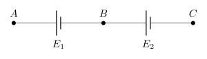
›Reveal solutionSolution
Balancing length is proportional to the p.d. being balanced, so lengths combine like voltages: ℓBC=∣ℓAC−ℓAB∣=∣8−64∣=56 cm. The answer is option (B).
The concept first: the potentiometer is a voltage ruler
A potentiometer works because the driver cell sets up a uniform potential gradient k (volts per cm) along the wire. When the galvanometer shows null deflection at length ℓ, the unknown p.d. exactly equals the p.d. across that stretch of wire:
V=kℓ
Because k is the same for every measurement on the same setup, length is a faithful stand-in for voltage. So any relation among the voltages translates, term for term, into the same relation among the lengths.
Step-by-step
Step 1 — Translate each measurement.
VAB=k(64),VAC=k(8)
Step 2 — Use the fact that potentials add along the path A→B→C.
VAC=VAB+VBC
Step 3 — Solve for VBC.
VBC=VAC−VAB=k(8)−k(64)=−56k …
- TG EAPCET 2022Set ap-2022-07-30-FN1 markMCQQ.A parallel plate capacitor of capacitance 8μF is connected to a 20V battery and is allowed to charge completely. The battery is then disconnected and a dielectric material of dielectric constant 8 is introduced between the plates of the capacitor. The energy dissipated in this process is (A) 1600μJ (B) 1400μJ (C) 1500μJ (D) 1200μJ
›Reveal solutionSolution
The key idea is that when the battery is disconnected, the charge on the capacitor is fixed. Inserting a dielectric reduces the electric field and thus the stored energy; the lost energy is dissipated as heat. The energy dissipated is 1400μJ, so the correct option is (B).
Concept and Intuition
When the battery is disconnected before inserting the dielectric, the capacitor plates are isolated, so the charge Q on them cannot change. The dielectric reduces the electric field inside the capacitor (by a factor equal to the dielectric constant K), which lowers the voltage between the plates and therefore reduces the stored electrostatic energy. Energy is conserved overall: the decrease in stored energy must appear as heat (or other forms of energy) — that’s the “energy dissipated.” The problem asks for that amount.
A common pitfall is to treat this as if the battery remained connected (where voltage stays constant and charge changes). Here, because the battery is removed, the charge is constant, not the voltage. That changes the calculation completely.
Step-by-step solution
- Find the initial charge and energy The capacitor is fully charged by the battery. Capacitance C0=8μF, battery voltage V0=20V. Charge stored:
Q=C0V0=(8×10⁻⁶)(20)=160μC.
Initial stored energy:
Ui=21C0V02=21(8×10⁻⁶)(20)2=21(8×10⁻⁶)(400)=1600μJ.
- After inserting the dielectric (battery disconnected) The dielectric constant K=8. With the battery disconnected, charge Q remains 160μC. The new capacitance becomes:
C=KC0=8×8μF=64μF.
The new voltage across the plates:
V=CQ=64μF160μC=2.5V.
The new stored energy:
Uf=21CV2=21(64×10−6)(2.5)2=21(64×10−6)(6.25)=200μJ.
- Energy dissipated The energy lost by the capacitor is the difference between initial and final stored energy:
- TG EAPCET 2022Set ap-2022-07-30-FN1 markMCQQ.A bulb and capacitor are connected in series to a source of alternating current. If frequency is increased, while keeping the voltage of the source constant, then (A) Bulb will give more intense light (B) Bulb will give less intense light (C) Bulb will give light of same intensity as before (D) Bulb light will fluctuate
›Reveal solutionSolution
For an RC series circuit driven by constant‑voltage AC, increasing the frequency reduces the capacitive reactance, which lowers the total impedance and increases the current, making the bulb brighter. The correct option is (A).
The key idea is that the bulb’s brightness depends on the power it dissipates, which is proportional to the square of the current through it. In an RC series circuit, the total impedance is Z=R2+XC2, where XC=ωC1=2πfC1. As frequency f increases, XC decreases, so Z decreases. With the source voltage fixed, the current I=V/Z increases, and the bulb glows more intensely.
- Identify the circuit behavior The bulb acts as a resistor R. The capacitor has reactance XC=ωC1. They are in series, so the total impedance is
Z=R2+(ωC1)2.
The source voltage V is constant.
-
Effect of increasing frequency
Angular frequency ω=2πf. When f increases, ω increases, so XC=1/(ωC) decreases. This makes the denominator Z smaller.
-
Current through the bulb
By Ohm’s law for AC circuits,
I=ZV.
Since Z decreases, I increases.
- Power dissipated in the bulb …
- TG EAPCET 2022Set eng-2022-07-18-AN1 markMCQQ.A 2μF capacitor is charged to 50V by a battery. The battery is removed after capacitor is fully charged. At time t=0, a 10mH coil is connected in series with the capacitor. The maximum rate at which the current changes in the circuit is (A) 2000A/s (B) 5000A/s (C) 2500A/s (D) 10000A/s
›Reveal solutionSolution
The maximum rate of change of current in an LC circuit occurs when the capacitor voltage is maximum, and equals LV0. Here, that gives 5000 A/s.
The key idea is that in an LC circuit (no resistance), the current oscillates sinusoidally. The rate of change of current, dtdi, is directly related to the voltage across the inductor by Faraday's law: VL=Ldtdi. Since the inductor and capacitor are in series, the voltage across the inductor equals the voltage across the capacitor at every instant (with opposite sign). So the maximum dtdi occurs when the capacitor voltage is maximum — which is the initial voltage 50 V, because there's no resistance to dissipate energy.
Let's work through it step by step.
-
Identify the circuit and the relevant physics. After the battery is removed and the coil is connected, we have a pure LC circuit. The capacitor is initially charged to V0=50 V with capacitance C=2 μF=2×10⁻⁶ F. The inductor has L=10 mH=10−2 H. There is no resistor, so the total energy oscillates between capacitor and inductor without loss.
-
Relate dtdi to the voltage. For an inductor, VL=Ldtdi. In the series LC loop, Kirchhoff's voltage law gives VC+VL=0, so VL=−VC. Therefore,
Ldtdi=−VC⇒dtdi=−LVC.
The magnitude of the rate of change of current is ∣dtdi∣=L∣VC∣.
- Find when ∣VC∣ is maximum. In an undamped LC oscillation, the capacitor voltage varies sinusoidally between +V0 and −V0. The maximum magnitude is V0=50 V, which occurs at t=0 (and again every half-period). So the maximum ∣VC∣ is simply the initial voltage. …
-
- TG EAPCET 2022Set eng-2022-07-19-FN1 markMCQQ.A resistor of resistance of 100 Ω is connected to an AC source ε=10sin(250 π s−1)t. The energy dissipated as heat during t=0 to t=1 ms is approximately. (A) π0.57 mJ (B) π1.141 mJ (C) 1 mJ (D) 0.5 mJ
›Reveal solutionSolution
Integrate the instantaneous power P=ε2/R over 0 to 1 ms. The heat dissipated is (21−π1)mJ=π0.57 mJ — option (A).
The interval 1 ms is only a fraction of the AC period, so the average power is not the full-cycle value; the energy must be found by direct integration of the instantaneous power.
1. Instantaneous power.
With ε(t)=10sin(250πt) (volts, t in seconds) and R=100 Ω,
P(t)=Rε(t)2=100100sin2(250πt)=sin2(250πt) W.
2. Energy integral.
E=∫010−3sin2(250πt)dt=21∫010−3[1−cos(500πt)]dt.
3. Evaluate.
E=21[t−500πsin(500πt)]010−3=21[10−3−500πsin(0.5π)].
Since sin(0.5π)=1, …
🎓Unlock everything free for 14 days
- ✓Full step-by-step solutions
- ✓Concept-first explanations
- ✓Methods, shortcuts & mistakes
- ✓PYQ mapping + timed mock tests
Full access for 14 days. No credit card required.