Physics · Ch 3 — Wave Optics
Interference of Light Waves and Young's Experiment
Interference of Light Waves and Young's Experiment
Why Two Independent Lamps Don't Produce Interference
Light from an ordinary source (like a sodium lamp) undergoes abrupt, random phase changes every seconds. If you try to use two separate sodium lamps to illuminate two pinholes and , the waves from each lamp have no fixed phase relationship — they are incoherent. In such a case, the intensities simply add up, and no interference pattern is seen on the screen.
Young's Clever Solution: Creating Coherent Sources
Thomas Young solved this problem by using a single source to produce two coherent secondary sources.
- A bright source illuminates a single pinhole .
- Light from spreads out and falls on two closely spaced pinholes and on an opaque screen.
- Since and are derived from the same original wavefront, any abrupt phase change at appears identically in both and .
- Thus, and act as two coherent sources — they are locked in phase, just like the two vibrating needles in the water wave example.
The spherical waves from and then interfere on a screen placed at a distance , producing alternating bright and dark bands called fringes.
Geometry of the Interference Pattern
Let:
- = separation between and
- = distance from the pinholes to the screen ()
- = wavelength of light
- = distance of a point on the screen from the central point
The path difference between waves from and reaching a point on the screen is approximately:
This approximation holds when and .
Conditions for Bright and Dark Fringes
Constructive interference (bright fringe) occurs when the path difference is an integer multiple of the wavelength:
Thus, the position of the -th bright fringe is:
Destructive interference (dark fringe) occurs when the path difference is a half-integer multiple of the wavelength:
Thus, the position of the -th dark fringe is: …
Drawn by us to help you understand the concept clearly, and verified to make sure it's accurate. For exams, practice from your textbook's own diagram.
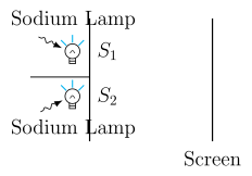
Fig. 10.11 shows a simple arrangement: two separate sodium lamps on the left, each one directly illuminating a single pinhole — lamp 1 lights pinhole , and lamp 2 lights pinhole . On the right is a screen. The light from each pinhole spreads out and falls on the screen.
The key physical idea is that the two sodium lamps are independent sources. In an ordinary source like a sodium lamp, the light wave undergoes abrupt, random phase changes every seconds or so. Because the two lamps are not linked, their phase changes are completely unrelated — they are incoherent. There is no fixed phase relationship between the waves from and .
As a result, the screen does not show alternating bright and dark bands (interference fringes). Instead, the intensities from the two sources simply add up at every point. The screen appears uniformly lit — the total intensity is just , with no variation.
This figure serves as a contrast to Young’s double-slit experiment (Fig. 10.12). In Young’s setup, a single source illuminates both and , making them coherent — their phases are locked together. Only then do interference fringes appear.
The textbook uses this figure to motivate the need for coherent sources. The formulas that follow (for Young’s experiment) give the positions of bright and dark fringes:
- For constructive interference (bright fringe):
- For destructive interference (dark fringe):
Here: …
Drawn by us to help you understand the concept clearly, and verified to make sure it's accurate. For exams, practice from your textbook's own diagram.
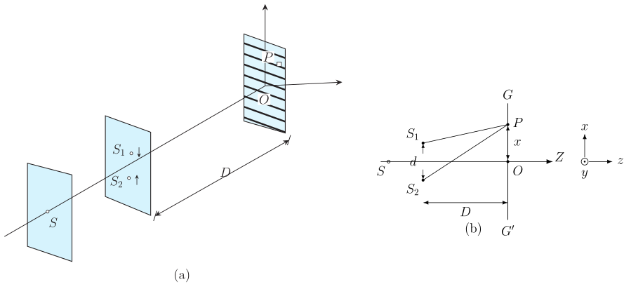
Fig. 10.12 is a schematic of Young’s double‑slit experiment, split into two panels to show both the geometry and the resulting interference pattern.
Panel (a) shows the essential layout. A bright source illuminates a single pinhole S on the left. Spherical waves spread from S and reach a second opaque screen that has two closely‑spaced pinholes S₁ and S₂. Because S₁ and S₂ are illuminated by the same wavefront from S, they act as coherent sources — their phases are locked together. The distance between S₁ and S₂ is labelled d (the slit separation). To the right of S₁ and S₂ is a screen GG′ placed at a large distance D from the pinholes. The geometry is such that the waves from S₁ and S₂ overlap on the screen.
Panel (b) depicts the result of that overlap. The spherical waves from S₁ and S₂ interfere, producing a pattern of equally‑spaced bright and dark fringes on GG′. The fringes are labelled directly on the screen. The bright fringes correspond to constructive interference (waves arrive in phase), and the dark fringes to destructive interference (waves arrive out of phase by half a wavelength).
Physical idea: The figure teaches that coherent sources (derived from a single source) are necessary to observe a stable interference pattern. The path difference between waves from S₁ and S₂ to a point on the screen determines whether the interference is constructive or destructive. For a point at a distance x from the central axis, the path difference is approximately (when ).
Key formulas developed from this figure:
- Bright fringes (constructive interference):
where is the wavelength of light, is the distance from the slits to the screen, and is the slit separation. …
Drawn by us to help you understand the concept clearly, and verified to make sure it's accurate. For exams, practice from your textbook's own diagram.
What the Figure Shows
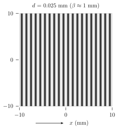
The figure is a computer-generated simulation of the interference pattern that appears on a screen in Young’s double-slit experiment. It depicts a rectangular strip of the screen, filled with a series of equally spaced vertical bright bands separated by dark bands. The pattern is symmetric about a central bright fringe, which is the brightest and most prominent band. The bright bands are labelled "bright fringe", the dark bands are labelled "dark fringe", and the central bright band is labelled "central maximum".
Physical Idea Taught
This figure visualises the interference of coherent light waves from two point sources and . When light from a single source passes through two closely spaced pinholes, the waves emerging from them are coherent (they have a fixed phase relationship). As these waves travel to different points on the screen, they superpose. At points where the path difference between the two waves is an integer multiple of the wavelength, constructive interference occurs, producing a bright fringe. At points where the path difference is a half-integer multiple of the wavelength, destructive interference occurs, producing a dark fringe. The equally spaced, alternating pattern of bright and dark bands is the hallmark of wave interference.
Key Formula Developed with This Figure
The textbook derives the positions of the fringes using the geometry of the setup. Let:
- = separation between the two slits and (here )
- = distance from the slits to the screen (here )
- = wavelength of light (here )
- = distance of a point on the screen from the central maximum
For constructive interference (bright fringe) at a distance from the centre:
Here is the order of the fringe. gives the central maximum. …