Q.A student connected the electrical components — voltmeter (V), ammeter (A), rheostat (Rh), and battery (B) — as shown in the figure, in order to verify Ohm's law. Identify the mistake(s) the student has made, and draw the circuit diagram formed by connecting the components correctly.
You're viewing a preview — the full solution, concept, methods & PYQ mapping are locked.
Start your 14-day free trial to unlock the full solution →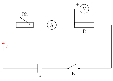
To verify Ohm's law, the ammeter must be in series (to read the current through R) and the voltmeter must be in parallel across R only (to read the potential difference across R); any deviation from this — e.g. the voltmeter not being connected directly across R alone, or wrong terminal polarities — is the mistake to fix.
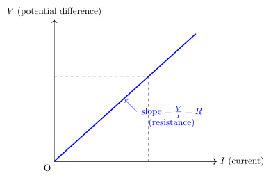
Correct method to verify Ohm's law: The resistor R, ammeter A, rheostat Rh, key K and battery B are all connected in series in one single loop (so the same current I flows through R and is read correctly by A), while the voltmeter V is connected separately, in parallel, directly across the two ends of R alone (not across any other combination) to read the potential difference V across R for that same current. The rheostat is used to vary the current in steps, and V/I is calculated at each setting; the ratio should stay constant, verifying Ohm's law. Additionally, the + terminals of both the ammeter and the voltmeter must face the terminal of the circuit from which current enters, otherwise the pointers will deflect backward.
…
Unlock everything free for 14 days
- Full step-by-step solutions
- Concept-first explanations
- Methods, shortcuts & mistakes
- PYQ mapping + timed mock tests
Full access for 14 days. No credit card required.