Informatics Practices · Ch 5 — Internet and Web
Bus Topology
Bus Topology
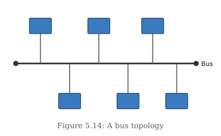
In bus topology, every device on the network connects to a single, shared communication line. That central cable is called the bus (or backbone). When one node sends data, the signal travels along the entire length of the bus in both directions. This means every other node connected to the bus can potentially receive that data — the bus acts as a common pathway for all communication.
Because all devices share just one main wire, bus topology is cheaper to set up and easier to maintain than topologies that require many separate connections. You only need to run a single cable and tap each device into it.
However, this simplicity comes with trade-offs. Both bus topology and ring topology are considered less secure and less reliable than other arrangements. If the main bus cable breaks at any point, the entire network stops working. Similarly, because every node can see all the traffic on the bus, it is harder to keep data private.
The textbook mentions that to build a fully-connected mesh topology with nodes, you would need wires. This is given as a contrast — bus topology uses far fewer wires than a mesh, which is why it is cheaper.
Key points to remember:
- All devices share a single backbone cable (the bus). …
Drawn by us to help you understand the concept clearly, and verified to make sure it's accurate. For exams, practice from your textbook's own diagram.
The figure shows a single horizontal line drawn across the centre of the diagram, labelled Bus. This line represents the common transmission medium — a single backbone wire that all devices share.
Several devices (typically drawn as small rectangles or circles) are positioned above and below this backbone. Each device is connected to the bus by a short vertical drop line that taps directly into the main horizontal cable. There are no hubs, switches, or central controllers in the diagram — every node connects independently to the same shared wire.
The layout is linear: the bus runs from one end of the figure to the other, and the devices are spaced out along its length. No arrows or directional markers appear on the bus itself, which visually reinforces the textbook's point that data placed on the bus travels in both directions simultaneously. Because every node is attached to the same cable, any data sent by one node reaches all other nodes — the diagram makes this clear by showing no barriers or terminators that would stop the signal.
The figure does not show terminators at the ends of the bus, though in practice a bus topology often requires them to prevent signal reflection. The NCERT diagram simplifies to focus on the core idea: a single shared cable with multiple direct taps. …