Physics · Ch 7 — Alternating Current
AC Voltage Applied to a Series LCR Circuit
AC Voltage Applied to a Series LCR Circuit
The Setup: Series LCR Circuit with AC Source
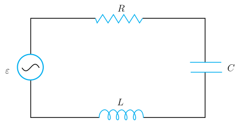
Consider a series circuit with an inductor (), a capacitor (), and a resistor () connected to an AC source. The source voltage varies sinusoidally with time:
Here:
- is the instantaneous voltage of the source.
- is the peak (maximum) voltage.
- is the angular frequency of the source.
- is time.
Let be the instantaneous charge on the capacitor and be the instantaneous current in the circuit.
Applying Kirchhoff's Loop Rule
Using Kirchhoff's voltage law for the closed loop, the sum of the voltage drops across the inductor, resistor, and capacitor must equal the applied source voltage at every instant.
- Voltage across inductor:
- Voltage across resistor:
- Voltage across capacitor:
This gives the governing equation:
Since current , we can rewrite the equation in terms of :
This is a second-order differential equation. The goal is to find the instantaneous current and its phase relationship with the applied voltage .
Two Methods of Solution
The textbook introduces two approaches to solve this: …
Drawn by us to help you understand the concept clearly, and verified to make sure it's accurate. For exams, practice from your textbook's own diagram.
The figure is a circuit diagram, not a plot. It shows a single closed rectangular loop with four components arranged in series:
- On the left side of the rectangle is the ac source, drawn as a circle containing a sine-wave symbol (∼). This source supplies an alternating voltage , where is the peak voltage and is the angular frequency.
- Along the top side is the resistor , represented by the standard zig-zag line.
- On the right side is the capacitor , shown as two parallel plates.
- Along the bottom side is the inductor , depicted as a coil (a series of loops).
The components are connected end-to-end in a single loop, so the same instantaneous current flows through all of them. The source, resistor, capacitor, and inductor are all in series.
Physical idea: The figure illustrates the simplest alternating-current circuit containing all three passive elements — resistance, inductance, and capacitance. The key lesson is that the total opposition to current is not just the sum of individual resistances; instead, the inductor and capacitor introduce phase differences between voltage and current, leading to the concept of impedance.
Key formula developed from this figure (Eq. 7.20 in the textbook):
where:
- = inductance (in henry),
- = instantaneous current (in ampere),
- = resistance (in ohm),
- = instantaneous charge on the capacitor (in coulomb),
- = capacitance (in farad),
- = peak source voltage (in volt),
- = angular frequency of the source (in rad/s),
- = time (in second). …