Physics · Ch 8 — Electromagnetic Waves
Displacement Current
Displacement Current
The Problem with Ampere's Law
Ampere's circuital law (from Chapter 4) states that the line integral of the magnetic field around a closed loop is proportional to the current passing through any surface bounded by that loop:
where is the permeability of free space and is the current through the surface.
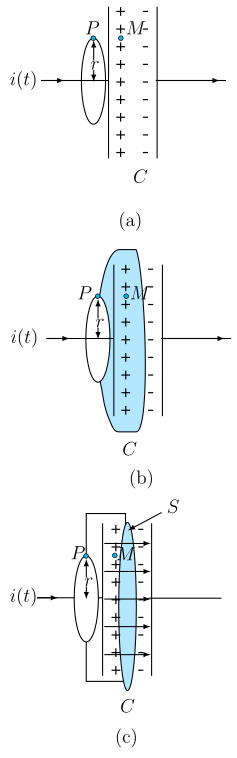
Consider a charging capacitor in a circuit with a time-dependent current . To find the magnetic field at a point outside the capacitor, we take a circular loop of radius centered on the wire. By symmetry, the magnetic field is tangential and constant in magnitude on this loop, so:
Now, consider a different surface with the same boundary (the same circular loop) — a pot-shaped surface that passes between the capacitor plates, never touching the wire. No conduction current passes through this surface. Applying Ampere's law to this surface gives:
This is a contradiction: the same loop gives two different values for the magnetic field at . Ampere's law must be missing a term.
The Missing Term: Displacement Current
What passes through the surface between the capacitor plates? The electric field!
For a parallel plate capacitor with plate area and charge , the electric field between the plates is:
The electric flux through the surface (the flat bottom of the tiffin-shaped surface between the plates) is:
If the charge changes with time, the current is . Differentiating the flux equation:
Rearranging:
This quantity has the same value as the conduction current and must be added to Ampere's law to resolve the contradiction.
Definition of Displacement Current
- Conduction current (): current due to flow of charges in conductors.
- Displacement current (): current due to changing electric field, defined as:
The total current is the sum:
The Ampere-Maxwell Law
The corrected, generalised form of Ampere's circuital law is:
This is called the Ampere-Maxwell law. It states that the source of a magnetic field is both conduction current and the time rate of change of electric field.
Physical Interpretation
- Outside the capacitor plates: only conduction current , displacement current . …
Drawn by us to help you understand the concept clearly, and verified to make sure it's accurate. For exams, practice from your textbook's own diagram.
What the Figure Shows
The figure has three panels, (a), (b), and (c), each showing the same parallel-plate capacitor C — two vertical plates, the left one with a column of + charges, the right with − charges. Short horizontal arrows between the plates indicate a uniform electric field pointing left to right. A horizontal wire enters from the left, carrying a time-dependent current (shown by an arrow). A point P is marked at the top-left of the plate gap, and a point M just inside the gap.
- Panel (a): A thin vertical ellipse (the Amperian loop) of radius encircles the wire near the plates. Point P lies on this loop. The loop is perpendicular to the wire and centered on it.
- Panel (b): The same loop now forms the mouth of a pot-shaped closed surface that bulges outward and dips its bottom between the capacitor plates, without touching the wire.
- Panel (c): The loop is the rim of a tiffin-box-shaped surface (flat-bottomed). Its flat circular bottom S lies between the capacitor plates, perpendicular to the electric field. The label S marks this flat bottom.
The Physical Idea
The figure illustrates a contradiction that arises when applying Ampere’s circuital law to a charging capacitor. The law states:
where is the conduction current through the surface bounded by the loop.
- In panel (a), the surface is the circular loop itself. The conduction current passes through it, so the law gives a nonzero magnetic field at P.
- In panels (b) and (c), the same loop is the rim of different surfaces. Neither surface is pierced by the conduction current (the wire does not go through them). Applying Ampere’s law to these surfaces would give zero magnetic field at P — a contradiction.
Maxwell resolved this by proposing that a changing electric field also produces a magnetic field. The missing term is the displacement current:
where is the electric flux through the surface. For the flat bottom S in panel (c), the electric field between the plates is uniform and perpendicular to S, so the flux is:
Thus, , exactly the conduction current. Adding this term makes the total current the same for any surface bounded by the loop, removing the contradiction.
Key Formula Developed
The generalised Ampere-Maxwell law is:
…
Drawn by us to help you understand the concept clearly, and verified to make sure it's accurate. For exams, practice from your textbook's own diagram.
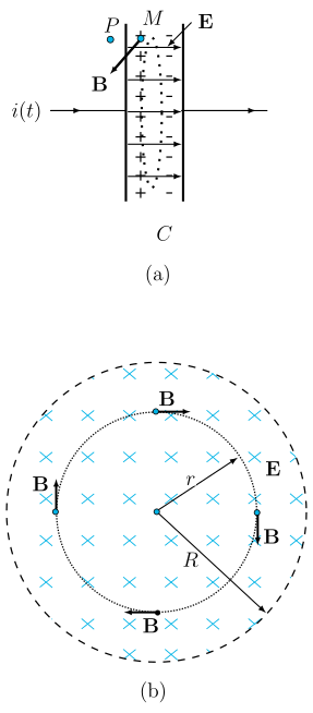
Figure 8.2 is a two‑panel diagram that shows the electric and magnetic fields inside a charging parallel‑plate capacitor. It is the key visual for understanding how a changing electric field acts as a source of magnetic field — the core idea of displacement current.
Panel (a) – Side view
- The capacitor has two parallel plates: the left plate carries positive charges (), the right plate negative charges ().
- A time‑varying conduction current enters from the left, so the charge on the plates is increasing with time.
- Point P is located just outside the capacitor (on the wire side), and point M is inside the gap between the plates.
- Between the plates, the electric field is drawn as a bold horizontal arrow pointing to the right — from the positive plate toward the negative plate. This field is uniform in the region between the plates (neglecting edge effects).
- At point M, a short vector is shown perpendicular to . This magnetic field is circular around the axis of the capacitor (into/out of the page in this side view). The diagram emphasises that even though there is no conduction current inside the gap, a magnetic field exists there — it is produced by the changing electric field.
Panel (b) – Cross‑sectional (end‑on) view
- This is a view looking along the axis of the capacitor, from the left plate toward the right plate.
- The electric field is represented by a disc filled with symbols — meaning points into the page (away from the viewer). A radial arrow of length is labelled , showing that the field is uniform across the disc.
- The magnetic field is drawn as circular arrows that are tangent to concentric dotted circles of radii and (labelled , ). The arrows indicate that circulates around the axis — it has no radial component.
- Bold labels are placed at several points on the circles, confirming that the magnitude of is constant on a given circle but varies with radius.
Physical idea
The figure teaches that a time‑varying electric field produces a magnetic field, just as a conduction current does. Inside the capacitor, there is no moving charge (conduction current ), yet a magnetic field is measured at point M. This magnetic field arises from the displacement current
where is the electric flux through a surface between the plates. The total current that acts as a source of is
Key formula developed with this figure
The Ampere‑Maxwell law (generalised Ampere’s law) is
- : line integral of magnetic field around a closed loop.
- : permeability of free space (). …