Q.Draw the ray diagram for the formation of image by a compound microscope.
You're viewing a preview — the full solution, concept, methods & PYQ mapping are locked.
Start your 14-day free trial to unlock the full solution →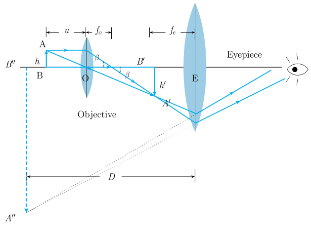
A compound microscope forms its final image in two stages: a real magnified image by the objective, further magnified as a virtual image by the eyepiece.
Main question — compound microscope ray diagram (described, since a diagram cannot be rendered here):
A compound microscope has two converging lenses: the objective (short focal length , facing the tiny object) and the eyepiece (larger focal length , near the eye).
[FIGURE: Compound microscope ray diagram — the object is placed just beyond the objective's focal point ; two rays from the top of the object are drawn through the objective — one parallel to the axis that refracts through (image-side focal point) and one through the optical centre undeviated — meeting to form a real, inverted, magnified image between the eyepiece and its focal point . This image then acts as the object for the eyepiece; rays from through the eyepiece (again one parallel to axis refracting through , one through the optical centre) diverge after the eyepiece and are traced backward to meet at the final image , a large, inverted, virtual image formed beyond the eyepiece, typically at the near point or at infinity.]
The objective forms a real, inverted, and magnified image of the object; this image lies within the focal length of the eyepiece, so the eyepiece acts like a simple magnifying glass on , producing a further magnified, virtual, and (relative to the object) inverted final image .
OR (alternative) — constructive and destructive interference:
When two coherent light waves superpose at a point: …
Unlock everything free for 14 days
- Full step-by-step solutions
- Concept-first explanations
- Methods, shortcuts & mistakes
- PYQ mapping + timed mock tests
Full access for 14 days. No credit card required.