Physics · Ch 10 — Wave Optics
Huygens Principle
Huygens Principle
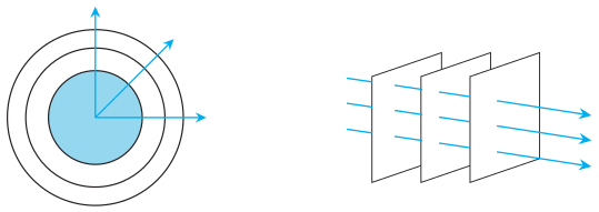
Wavefront
A wavefront is a surface of constant phase. All points on a wavefront oscillate in phase. For a point source emitting waves uniformly in all directions, the wavefronts are spheres (spherical wave). At a large distance from the source, a small portion of a spherical wavefront can be approximated as a plane (plane wave).
The speed with which the wavefront moves outward is the wave speed. The energy of the wave travels in a direction perpendicular to the wavefront.
Huygens Principle
Huygens principle is a geometrical construction that allows us to determine the shape of a wavefront at a later time, given its shape at an earlier time.
Key statements of the principle:
- Every point on a given wavefront acts as a source of secondary disturbances (called secondary wavelets).
- These secondary wavelets spread out in all directions with the speed of the wave in the medium.
- The envelope (common tangent) of all these secondary wavelets gives the new position of the wavefront at a later time.
Construction for a Spherical Wavefront
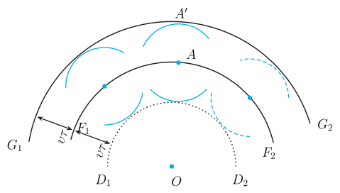
Consider a diverging spherical wavefront at time , with centre .
- At time , each point on acts as a source of secondary wavelets.
- Each wavelet travels a distance in the medium, where is the wave speed.
- Draw spheres of radius from every point on .
- The common tangent (envelope) to all these spheres gives the new wavefront at time .
The new wavefront is again spherical with the same centre .
The Backwave Problem
Huygens construction also produces a backward wavefront (the envelope on the opposite side). To explain why this backwave is not observed, Huygens made an ad hoc assumption:
The amplitude of the secondary wavelets is maximum in the forward direction and zero in the backward direction.
This assumption is not rigorous but is justified by more advanced wave theory.
Construction for a Plane Wavefront …
Drawn by us to help you understand the concept clearly, and verified to make sure it's accurate. For exams, practice from your textbook's own diagram.
Figure 10.1 has two panels that contrast the geometry of wavefronts near and far from a point source.
Panel (a) shows a point source at the centre. Concentric spherical wavefronts radiate outward — these are surfaces of constant phase, meaning every point on a given sphere oscillates in the same phase. Short radial arrows (rays) are drawn perpendicular to each wavefront, indicating the direction of energy propagation. The wavefronts are spherical because the source emits uniformly in all directions.
Panel (b) zooms in on a small region far from the source. Here, the spherical wavefronts appear nearly flat — drawn as parallel straight lines. The rays are also parallel and perpendicular to these plane wavefronts. This illustrates the plane wave approximation: at large distances, a small patch of a spherical wave can be treated as a plane wave.
Physical idea: The figure introduces the concept of a wavefront — a surface of constant phase — and shows how the same wave can be described as spherical near the source and planar far away. This sets the stage for Huygens principle, which uses wavefront geometry to predict wave propagation.
Key formula developed from this figure: The speed of the wave relates the distance a wavefront travels in time to the radius of the spherical wavefront:
where:
- is the radius of the spherical wavefront (distance from the source),
- is the wave speed in the medium,
- is the time elapsed since the wave left the source. …
Drawn by us to help you understand the concept clearly, and verified to make sure it's accurate. For exams, practice from your textbook's own diagram.
What the Figure Shows
The figure illustrates Huygens principle for a spherical wave diverging from a point source O. At time , the wavefront is the spherical arc F₁F₂ — a surface of constant phase centered at O. From several points on this arc, small secondary wavelets are drawn as circles of radius , where is the wave speed and is the time elapsed. The common forward tangent to all these circles is the new wavefront G₁G₂ at time , which is also a spherical arc centered at O but farther away. A dashed inner arc D₁D₂ represents the backwave — the envelope of the backward halves of the secondary wavelets — which Huygens argued does not exist in reality.
Physical Idea Taught
The figure demonstrates the core of Huygens principle: every point on a wavefront acts as a source of secondary spherical wavelets. The new wavefront is the envelope of these wavelets. For a diverging spherical wave, the construction correctly predicts that the wavefront remains spherical and expands outward. The backwave (D₁D₂) is an artifact of the simple geometric construction; Huygens made the ad hoc assumption that secondary wavelets have zero amplitude in the backward direction, which is later justified by rigorous wave theory.
Key Formula Developed
The radius of each secondary wavelet is:
where:
- = speed of the wave in the medium (m/s)
- = time elapsed since the original wavefront () …
Drawn by us to help you understand the concept clearly, and verified to make sure it's accurate. For exams, practice from your textbook's own diagram.
What the Figure Shows
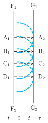
The diagram illustrates Huygens' geometrical construction for a plane wave moving to the right. At time , the wavefront is a vertical straight line labelled F₁F₂. This represents a surface of constant phase — all points along F₁F₂ are oscillating in phase.
From several points on F₁F₂, secondary wavelets are drawn as semicircles of radius , where is the wave speed and is the elapsed time. These semicircles represent the spherical wavelets that each point on the original wavefront emits, according to Huygens' principle.
The common tangent to all these semicircles is the new wavefront at time , labelled G₁G₂. It is also a vertical straight line, shifted to the right by a distance . This shows that the plane wave has advanced uniformly.
The rays are drawn as horizontal lines (e.g., A₁A₂, B₁B₂, …) that are perpendicular to both F₁F₂ and G₁G₂. They indicate the direction of energy propagation — from left to right.
Physical Idea Taught
The figure demonstrates Huygens' principle for a plane wave: every point on a wavefront acts as a source of secondary spherical wavelets. The envelope (common tangent) of these wavelets gives the new wavefront at a later time. For a plane wave, the new wavefront remains a plane parallel to the original, shifted forward by .
This construction explains why plane waves travel in straight lines (rays) perpendicular to the wavefronts, and why the wavefronts remain planar in a uniform medium.
Key Formula Developed
The distance the wavefront moves in time is:
…