Physics · Ch 9 — Mechanical Properties of Fluids
Hydraulic Machines
Hydraulic Machines
9.2.4 Hydraulic Machines
The principle that pressure applied to an enclosed fluid is transmitted undiminished to every part of the fluid — Pascal's law — has a direct and powerful application in hydraulic machines. These devices use a liquid (usually oil or water) to multiply force, allowing a small input force to lift or move a very heavy load.
The Core Idea: Force Multiplication
Consider a simple hydraulic system consisting of two cylinders of different cross-sectional areas, connected by a pipe filled with an incompressible fluid. Each cylinder is fitted with a tight-fitting piston.
If you push down on the smaller piston with a force , you create a pressure in the fluid:
where is the area of the small piston. Because the fluid is enclosed and incompressible, Pascal's law tells us that this same pressure acts everywhere in the fluid — including on the larger piston of area . The force exerted by the fluid on the larger piston is therefore:
Since , the output force is larger than the input force by the factor . This ratio is called the mechanical advantage of the hydraulic machine.
The force multiplication comes at a cost. The work done by the input piston () equals the work done by the output piston (), assuming no friction. Since , the output piston moves a smaller distance: . You cannot get more work out than you put in — energy is conserved.
The Hydraulic Lift
The most common example is a hydraulic lift used in garages to raise cars. A small piston (the "master cylinder") is connected by a pipe to a large piston (the "slave cylinder") under the lift platform. A small force on the master piston generates a large force on the slave piston, lifting the vehicle.
In practice, the system uses a valve and a reservoir of oil. The operator pumps the small piston repeatedly; each stroke forces oil into the large cylinder, gradually raising the load. The valve prevents the oil from flowing back when the small piston is raised for the next stroke.
The Hydraulic Brake
Another vital application is the hydraulic braking system in automobiles. When the driver presses the brake pedal, it pushes a piston in the master cylinder. This creates pressure in the brake fluid (a special oil). The pressure is transmitted through the fluid lines to each wheel, where it pushes pistons in the brake calipers or wheel cylinders. These pistons press the brake pads against the rotating disc (or the brake shoes against the drum), creating friction that slows the wheel.
The key advantage is that the pressure is transmitted equally to all four wheels simultaneously, ensuring balanced braking. Also, the mechanical advantage from the pedal leverage and the piston area ratios multiplies the driver's foot force. …
Drawn by us to help you understand the concept clearly, and verified to make sure it's accurate. For exams, practice from your textbook's own diagram.
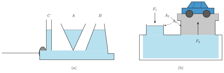
Figure 9.6 in the NCERT textbook is actually two separate diagrams, labelled (a) and (b), that together illustrate one of the most important principles in fluid mechanics: Pascal’s law.
Panel (a) shows a horizontal cylinder with a piston on the left side. Three vertical tubes — labelled C, A, and B — rise from the cylinder at different positions. The liquid inside the cylinder and tubes is at the same height in all three tubes. This is the key visual: no matter where along the cylinder you place a vertical tube, the liquid level is identical. The piston is used to apply an external force to the fluid.
What this diagram teaches is that pressure applied at one point in a confined fluid is transmitted undiminished to every part of the fluid. When you push the piston, the liquid level in all three tubes rises by the same amount — not more in the tube nearest the piston, not less in the farthest one. The pressure increase is exactly the same at C, A, and B. This is the physical content of Pascal’s law: a change in pressure applied to an enclosed fluid is transmitted equally throughout the fluid.
Pascal’s law: applied anywhere in a confined fluid produces the same at every point.
Panel (b) shows the practical application: a hydraulic lift. There are two pistons connected by a liquid-filled container. On the left is a small piston of area with a force applied downward. On the right is a large piston of area supporting a platform that carries a car; the upward force on this piston is .
The physics is a direct consequence of panel (a). The pressure increase produced by the small piston is . Because the fluid is confined, this same pressure increase acts on the large piston. The force on the large piston is therefore .
Here is the input force, the area of the small piston, the area of the large piston, and the output force. Since , the output force is larger than the input force by the ratio of the areas. This is the principle behind hydraulic brakes, hydraulic jacks, and the hydraulic lift shown in the figure — a small force applied over a small area can lift a heavy load. …