Physics · Ch 6 — Electromagnetic Induction
The Experiments of Faraday and Henry
The Experiments of Faraday and Henry
The Core Idea: Changing Magnetic Fields Create Current
The experiments of Faraday and Henry reveal a fundamental principle: a changing magnetic field can induce an electric current in a nearby conductor. The key is change — a steady magnetic field produces no current. This phenomenon is called electromagnetic induction.
Experiment 1: Magnet and Coil
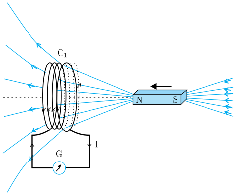
A coil () is connected to a galvanometer (G), which detects current.
- Motion matters: When a bar magnet is pushed towards the coil, the galvanometer deflects, showing current flows. The deflection lasts only while the magnet is moving.
- Stationary = no current: Holding the magnet still produces zero deflection.
- Direction reversal: Pulling the magnet away from the coil gives a deflection in the opposite direction — the induced current reverses.
- Pole reversal: Using the South-pole instead of the North-pole reverses the deflection direction for the same motion.
- Speed effect: Moving the magnet faster produces a larger deflection (larger current).
- Relative motion: The same effects occur if the coil is moved while the magnet stays fixed. Only relative motion between magnet and coil matters.
Conclusion: A changing magnetic field (due to relative motion) induces current in the coil.
Experiment 2: Two Coils — One with Current
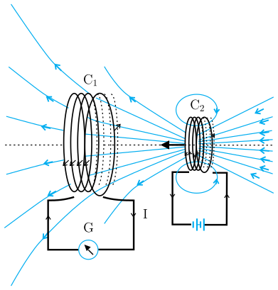
The bar magnet is replaced by a second coil () connected to a battery, producing a steady magnetic field.
- Moving : When (carrying steady current) is moved towards coil , the galvanometer deflects — current is induced in .
- Moving away: Moving away gives a deflection in the opposite direction.
- Motion only: Deflection lasts only while is moving.
- Relative motion again: Moving while is fixed gives the same results.
Conclusion: A changing magnetic field (due to relative motion between two coils) induces current, even when the source of the field is another current-carrying coil.
Experiment 3: No Relative Motion — Changing Current
Faraday showed that relative motion is not essential. Here, both coils are held stationary.
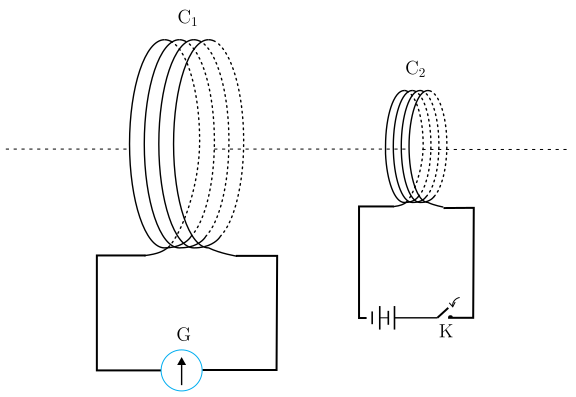
- Setup: Coil is connected to a galvanometer. Coil is connected to a battery through a tapping key (K).
- Pressing the key: When K is pressed, the galvanometer shows a momentary deflection — current is induced in for an instant.
- Steady current: If K is held pressed, the current in is steady, and the galvanometer shows no deflection.
- Releasing the key: When K is released, a momentary deflection occurs again, but in the opposite direction.
- Iron rod effect: Inserting an iron rod along the axis of both coils dramatically increases the deflection. …
Drawn by us to help you understand the concept clearly, and verified to make sure it's accurate. For exams, practice from your NCERT textbook's own diagram.
What the Figure Shows
The diagram depicts a coil — drawn as a stack of concentric ellipses seen edge-on — connected by two wires to a galvanometer (a circle with a deflected needle). To the right of the coil, along a horizontal dashed axis, lies a bar magnet (shaded rectangle) with its North pole (N) facing the coil and its South pole (S) at the far right. A short arrow above the magnet points left, indicating the magnet is being pushed toward the coil. Blue magnetic field lines emerge from the N-pole and from the coil, curving outward to the upper-left and lower-left, with arrowheads showing direction. The right wire from the coil carries a downward arrow labelled I (induced current).
The Physical Idea
The figure illustrates Faraday’s first experiment: when the North pole of a bar magnet is moved toward a stationary coil, the galvanometer needle deflects — showing that an electric current is induced in the coil. The deflection lasts only while the magnet is in motion; if the magnet is held still, the needle returns to zero. This demonstrates that relative motion between the magnet and the coil is essential for generating induced current. The direction of deflection (and hence current) reverses when the magnet is pulled away, or when the South pole is used instead.
Key Formula Developed from This Figure
From this experiment, Faraday’s law of electromagnetic induction is derived:
where:
- is the induced emf (electromotive force) in the coil (in volts),
- is the magnetic flux through the coil (in webers), given by ,
- is the rate of change of magnetic flux with time,
- The negative sign (Lenz’s law) indicates that the induced emf opposes the change in flux.
For a coil with turns, the formula becomes: …
Drawn by us to help you understand the concept clearly, and verified to make sure it's accurate. For exams, practice from your NCERT textbook's own diagram.
What the diagram shows
The figure depicts two coaxial disc‑shaped coils placed along a common dashed horizontal axis. On the left is a larger coil labelled C₁, drawn as a stack of ellipses. On the right is a smaller coil labelled C₂. Blue magnetic field lines radiate from C₂ toward C₁, fanning outward in the upper‑left and lower‑left directions. A black arrow pointing leftward between the coils indicates that C₂ is moving toward C₁. Below C₁, two leads drop to a rectangular box containing a circular galvanometer G, with a downward‑pointing arrow labelled I (the induced current). Below C₂, its leads form a loop that includes a battery symbol (two unequal parallel lines). The arrangement mirrors Fig. 6.1, with the bar magnet replaced by the current‑carrying coil C₂.
Physical idea taught
The figure illustrates Faraday’s experiment 6.2: a steady current in coil C₂ produces a steady magnetic field. When C₂ is moved toward C₁, the magnetic flux through C₁ changes, inducing an electric current in C₁ that is detected by the galvanometer. The deflection lasts only while C₂ is in motion; when C₂ is stationary, no current is induced. Reversing the direction of motion (moving C₂ away) reverses the deflection, showing that the induced current’s direction depends on whether the flux is increasing or decreasing. The key insight is that relative motion between the coils — not the presence of a permanent magnet — is sufficient to induce current.
Key formula developed from this figure
The textbook uses this experiment to introduce Faraday’s law of induction. The induced electromotive force (emf) in coil C₁ is given by:
where:
- is the induced emf (in volts),
- is the magnetic flux through coil C₁ (in webers),
- is the rate of change of that flux with time,
- the negative sign indicates the direction of the induced emf (Lenz’s law). …
Drawn by us to help you understand the concept clearly, and verified to make sure it's accurate. For exams, practice from your NCERT textbook's own diagram.
What the Figure Shows
The diagram depicts two stationary coaxial coils — a large multi-turn coil on the left and a smaller coil on the right. A long dashed horizontal line runs through their centres, indicating they share a common axis. There are no motion arrows anywhere; both coils are fixed in place.
Below , two leads connect to a rectangular box containing a galvanometer (drawn as a circle with an upward-pointing needle). Below , the leads form a loop that includes a battery symbol on the left and a tapping key (an open switch with a contact dot) on the right. The key is the only active element — it can be pressed (closed) or released (opened).
The Physical Idea
This figure illustrates Faraday’s Experiment 6.3, which shows that relative motion between a magnet and a coil is not necessary to induce an electric current. Instead, a changing magnetic field is the essential requirement.
When the key is pressed, current from the battery begins to flow through , building up its magnetic field. This changing magnetic field (from zero to a steady value) passes through , inducing a momentary current in — seen as a brief deflection of the galvanometer needle. Once the current in becomes steady, the magnetic field stops changing, and the galvanometer returns to zero.
When the key is released, the current in drops to zero, causing the magnetic field to decrease. This change again induces a momentary current in , but in the opposite direction — the galvanometer needle deflects the other way.
The effect is dramatically enhanced when an iron rod is inserted along the axis of both coils, because iron increases the magnetic field strength and concentrates the flux.
Key Formula Developed from This Figure
The textbook uses this experiment to introduce Faraday’s law of induction. The induced electromotive force (emf) in coil is given by:
where:
- is the induced emf (in volts) in coil ,
- is the magnetic flux through coil (in webers),
- is the rate of change of that flux with time, …