Q.A sinusoidal voltage of peak value 283 V and frequency 50 Hz is applied to a series LCR circuit in which R=3 Ω, L=25.48 mH, and C=796 μF. Find
Concept understanding — Power Dissipation in Resistors
Power Dissipation in Resistors
Whenever charge is driven through a resistor, electrical energy is converted into heat. The rate of this conversion is the power dissipated.
Why a Resistor Heats Up
Inside a resistor, drifting electrons repeatedly collide with the vibrating lattice ions. Each collision transfers kinetic energy to the lattice, raising its temperature. The source (battery or AC supply) continually does work to keep the current flowing, and that work reappears as heat. This is Joule heating.
The Power Formulas (DC)
The power delivered to any device carrying current I across a potential difference V is
P=VI
For an ohmic resistor V=IR, so this can be written in three equivalent forms:
P=VI=I2R=RV2
The SI unit is the watt (W), where 1 W=1 J s−1.
Which form to use depends on what is fixed:
- Series elements share the same current, so P=I2R shows the larger resistor dissipates more.
- Parallel elements share the same voltage, so P=V2/R shows the smaller resistor dissipates more.
The total heat produced in time t is Q=Pt=I2Rt — Joule's law of heating.
Power Dissipation with AC
With alternating current the instantaneous power p(t)=i2(t)R fluctuates, but a resistor still only dissipates energy (it never returns any). The average power over a cycle is written with root-mean-square values:
Pavg=Irms2R=RVrms2=VrmsIrms
where for a sinusoid Irms=Im/2 and Vrms=Vm/2. This is precisely why rms values are defined: an AC of rms value Irms heats a resistor at the same average rate as a steady DC of value Irms.
A pure resistor has power factor 1 — voltage and current are in phase, so all the power supplied is dissipated. In inductors and capacitors, by contrast, the average dissipated power is zero; energy is only stored and returned.
Worked Example
A 100 Ω resistor carries a current of 0.5 A.
P=I2R=(0.5)2×100=25 W
In one minute it releases Q=Pt=25×60=1500 J of heat.
Do not mix peak and rms quantities. Using peak AC values in P=V2/R overestimates the average power by a factor of two for a sinusoid.
Everyday Relevance
Electric heaters, incandescent bulbs and fuses all rely on controlled I2R heating, while transmission engineers fight to minimise it — sending power at high voltage keeps I small and cuts the I2R line losses.
Power dissipation in resistors through Joule heating, P = I²R = V²/R, spans the NCERT Class 12 Physics chapters on current electricity and alternating current, and is one of the most frequently numerically tested formulas in CBSE boards, JEE Main and NEET. Searches for "power dissipated in a resistor formula rms value class 12 physics" will find this DC-and-AC comparison matches the NCERT-prescribed treatment.
Why this formula?
Power Dissipation in Resistors — Why the Formula Holds
Let's build this from first principles. The goal is to understand why a resistor dissipates power as heat, and how the formula P=I2R (and its equivalents) arise naturally.
1. What is "Power" in an Electrical Circuit?
Power is the rate of energy transfer — how much energy is converted from one form to another per unit time.
- In a resistor, electrical energy is converted into heat (thermal energy).
- The fundamental definition of electrical power is:
P=V⋅I
where:
- P = power (watts, W)
- V = voltage across the component (volts, V)
- I = current through the component (amperes, A)
Why this definition?
Voltage is energy per unit charge (V=qW), and current is charge per unit time (I=tq). Multiplying them gives energy per unit time — exactly power.
2. How Does a Resistor Behave? — Ohm's Law
A resistor obeys Ohm's Law:
V=I⋅R
where R is resistance (ohms, Ω). This is an empirical law — it describes how real resistors behave: the voltage across them is proportional to the current through them.
3. Deriving the Power Dissipation Formulas
We start with P=VI and substitute Ohm's Law in two ways.
Case A: Express power in terms of I and R
Replace V with IR:
P=(IR)⋅I=I2R
Interpretation:
- For a fixed resistance, power grows with the square of current.
- Doubling current quadruples the heat generated — this is why high currents cause wires to overheat.
Case B: Express power in terms of V and R
Replace I with RV:
P=V⋅(RV)=RV2
Interpretation:
- For a fixed voltage, power is inversely proportional to resistance.
- A low-resistance resistor (like a short circuit) dissipates huge power at a given voltage — that's why short circuits are dangerous.
4. The Physical "Why" — Energy Conversion at the Atomic Level
Why does this energy turn into heat?
- Electrons moving through a resistor collide with the atoms of the material.
- Each collision transfers kinetic energy from the electron to the atom, making the atom vibrate more — i.e., heating up the resistor.
- The rate at which this energy is lost by the electrons (and gained by the lattice) is exactly P=I2R.
Key insight:
The I2 term appears because:
- More current = more electrons per second.
- Each electron loses more energy if resistance is higher (more collisions per electron).
5. Summary of Key Formulas
| Formula | When to use |
|---|---|
| P=VI | Fundamental — always true for any circuit element |
| P=I2R | Best when you know current and resistance |
| P=RV2 | Best when you know voltage and resistance |
All three are equivalent for resistors obeying Ohm's Law.
6. Exam Tip — Common Mistake
Never mix formulas across different components:
- For a resistor, all three forms work.
- For a diode or battery, only P=VI holds — Ohm's Law does not apply, so I2R would be wrong.
Remember: The derivation starts from P=VI, then uses Ohm's Law. If the component doesn't follow Ohm's Law, the derived forms are invalid.
Final takeaway: Power dissipation in a resistor is the rate at which electrical energy is converted to heat, given by P=I2R because voltage and current are linked by resistance. The I2 factor explains why even small increases in current cause large heating effects — a critical concept for circuit safety and design.
Concept: Power Dissipation in Resistors — in an AC circuit, only the resistor dissipates power; the average power is P=VrmsIrmscosϕ=Irms2R.
Step 1 — Reactances and impedance
Inductive reactance:
XL=2πfL=2π(50)(25.48×10⁻³)=8 Ω
Capacitive reactance:
XC=2πfC1=2π(50)(796×10−6)1=4 Ω
Net reactance: X=XL−XC=4 Ω
Impedance: Z=R2+X2=32+42=5 Ω
Step 2 — Phase difference and power factor
tanϕ=RX=34⇒ϕ=tan−1(34)≈53.13∘ (voltage leads current)
Power factor: cosϕ=ZR=53=0.6
Step 3 — Power dissipated
RMS voltage: Vrms=2283≈200 V
RMS current: Irms=ZVrms=5200=40 A
Power: P=Irms2R=(40)2(3)=4800 W
- Impedance is 5 Ω;
- phase difference is 53.13∘ (voltage leads);
- power dissipated is 4800 W;
- power factor is 0.6.
For a series LCR circuit driven by an AC source, the impedance is the vector sum of resistance and net reactance. Here, XL=8 Ω, XC=4 Ω, so net reactance X=4 Ω, giving impedance Z=5 Ω. The phase angle ϕ=tan−1(X/R)=53.13∘ (voltage leads current). Power factor cosϕ=0.6, and power dissipated P=VrmsIrmscosϕ=4800 W.
Concept and Intuition
In a series LCR circuit, the resistor, inductor, and capacitor each oppose current in different ways. Resistance R dissipates energy as heat. Inductive reactance XL=ωL and capacitive reactance XC=1/(ωC) store and release energy but do not dissipate it — they merely cause a phase shift between voltage and current.
The total opposition to current is impedance Z, given by:
Z=R2+(XL−XC)2
The phase difference ϕ tells us whether the circuit behaves more like an inductor (voltage leads current, ϕ>0) or a capacitor (current leads voltage, ϕ<0):
tanϕ=RXL−XC
Power is only dissipated in the resistor. The average power over a cycle is:
P=VrmsIrmscosϕ
where cosϕ is the power factor.
Step-by-Step Solution
1. Find the angular frequency ω
Given frequency f=50 Hz:
ω=2πf=2π×50=100π rad/s
2. Calculate inductive reactance XL
L=25.48 mH=25.48×10⁻³ H
XL=ωL=100π×25.48×10−3
Using π≈3.14:
XL=100×3.14×25.48×10−3=314×0.02548≈8.00 Ω
Notice 25.48×3.14≈80.0, then divide by 1000 gives exactly 8 Ω. This neat round number is common in exam problems.
3. Calculate capacitive reactance XC
C=796 μF=796×10−6 F
XC=ωC1=100π×796×10−61
First compute ωC=100π×796×10−6=314×796×10−6
314×796≈250,000 (since 314×800=251,200, minus 314×4=1,256 gives 249,944)
So ωC≈0.25
XC=0.251=4.00 Ω
4. Compute net reactance X
X=XL−XC=8−4=4 Ω
The circuit is inductive (positive reactance).
5. Find impedance Z
Z=R2+X2=32+42=9+16=25=5 Ω
Z=R2+(XL−XC)2
6. Determine phase difference ϕ
tanϕ=RX=34⇒ϕ=tan−1(34)≈53.13∘
Since XL>XC, voltage leads current by 53.13∘.
7. Calculate rms values of source voltage and current
Peak voltage V0=283 V
Vrms=2V0=1.414283≈200 V
A common mistake is to use peak values directly in power formulas. Always convert to rms for AC power calculations.
Irms=ZVrms=5200=40 A
8. Find power factor
Power factor=cosϕ=ZR=53=0.6
9. Compute power dissipated
P=VrmsIrmscosϕ=200×40×0.6=4800 W
Alternatively, since only the resistor dissipates power:
P=Irms2R=402×3=1600×3=4800 W
The I2R formula is often quicker and avoids needing the power factor separately — but both give the same result.
- Impedance Z=5 Ω;
- Phase difference ϕ=53.13∘ (voltage leads current);
- Power dissipated P=4800 W;
- Power factor cosϕ=0.6.
Method: Phasor Analysis of Series LCR Circuit
This method uses phasor diagrams and impedance triangle to solve AC circuit problems step-by-step.
Step 1: Find Inductive and Capacitive Reactance
Given:
- V0=283 V, f=50 Hz
- R=3 Ω, L=25.48 mH=25.48×10⁻³ H
- C=796 μF=796×10−6 F
Angular frequency:
ω=2πf=2π×50=100π rad/s
Inductive reactance:
XL=ωL=100π×25.48×10−3
XL=100×3.1416×25.48×10−3≈8 Ω
Capacitive reactance:
XC=ωC1=100π×796×10−61
XC≈4 Ω
Step 2: Calculate Impedance (Part a)
Net reactance:
X=XL−XC=8−4=4 Ω
Impedance magnitude:
Z=R2+X2=32+42=9+16=25
Z=5 Ω
Step 3: Find Phase Difference (Part b)
Phase angle ϕ (voltage leads current if XL>XC):
tanϕ=RX=34
ϕ=tan−1(34)≈53.13∘
Since XL>XC, voltage leads current by 53.13∘.
Step 4: Compute Power Dissipated (Part c)
RMS voltage:
Vrms=2V0=2283≈200 V
RMS current:
Irms=ZVrms=5200=40 A
Power dissipated (only in resistor):
P=Irms2R=(40)2×3=4800 W
Step 5: Determine Power Factor (Part d)
Power factor:
cosϕ=ZR=53=0.6 (lagging)
The power factor is lagging because the circuit is inductive (XL>XC).
Quick Verification
- P=VrmsIrmscosϕ=200×40×0.6=4800 W ✓
Final Answers:
- (a) Z=5 Ω
- (b) ϕ=53.13∘ (voltage leads current)
- (c) P=4800 W
- (d) cosϕ=0.6 (lagging)
Here are the common mistakes students make when solving this exact problem, along with how to avoid each.
Mistake 1: Forgetting to convert units (mH, μF → H, F)
The mistake:
Plugging L=25.48 and C=796 directly into formulas without converting to henries and farads.
How to avoid:
Always write the conversion step explicitly:
- L=25.48 mH=25.48×10⁻³ H
- C=796 μF=796×10−6 F
Check: If you get an impedance near 3 Ω, you likely converted correctly. If it’s huge or tiny, re-check units.
Mistake 2: Using peak voltage (V0) in RMS formulas for power
The mistake:
Using P=RV02 or P=V0I0cosϕ directly — these give peak power, not average power.
How to avoid:
Remember: Power dissipation in AC circuits uses RMS values.
- Vrms=2V0=2283≈200 V
- Average power: P=VrmsIrmscosϕ or P=Irms2R
Key fact: Only Irms2R gives the correct average power dissipated.
Mistake 3: Confusing phase difference sign (ϕ)
The mistake:
Writing ϕ=tan−1(RXL−XC) but then using the wrong sign when calculating power factor.
How to avoid:
- XL=ωL, XC=ωC1
- If XL>XC, ϕ>0 (voltage leads current — inductive circuit)
- If XL<XC, ϕ<0 (voltage lags current — capacitive circuit)
- Power factor cosϕ is always positive (use ∣ϕ∣ or cosϕ=ZR directly)
Tip: Use cosϕ=ZR — it’s foolproof and avoids sign errors.
Mistake 4: Forgetting ω=2πf (not f)
The mistake:
Using f=50 Hz directly in XL=ωL as XL=fL.
How to avoid:
Always write:
ω=2πf=2π×50=100π rad/s
Then:
XL=ωL=100π×25.48×10−3
XC=ωC1=100π×796×10−61
Mistake 5: Calculating impedance Z incorrectly
The mistake:
Writing Z=R+(XL−XC) or Z=R2+XL2+XC2.
How to avoid:
The correct formula is:
Z=R2+(XL−XC)2
Why: XL and XC are opposite in phase — they subtract, not add.
Mistake 6: Using P=VrmsIrms without cosϕ
The mistake:
Assuming P=VrmsIrms gives power dissipated.
How to avoid:
In an LCR circuit, voltage and current are out of phase. The true power is:
P=VrmsIrmscosϕ
Only the resistive component dissipates power.
Alternative (safer):
P=Irms2R
This automatically accounts for phase — no cosϕ needed.
Mistake 7: Rounding too early
The mistake:
Rounding intermediate values (e.g., XL, XC, Z) to 2–3 digits, then getting a final answer that’s off.
How to avoid:
Keep at least 4 significant figures in intermediate steps. Round only the final answer.
Example:
- XL=100π×0.02548≈8.004 Ω (not 8.0)
- XC=100π×796×10−61≈4.000 Ω (not 4.0)
- Then XL−XC=4.004 Ω, Z=32+4.0042≈5.00 Ω
Quick Summary Checklist
| Step | Common Mistake | Fix |
|---|---|---|
| Units | Use mH/μF directly | Convert to H/F |
| Voltage | Use V0 for power | Use Vrms=V0/2 |
| ω | Use f instead | ω=2πf |
| Z | Add XL and XC | Subtract: XL−XC |
| Power | P=VI | P=Irms2R or P=VrmsIrmscosϕ |
| Rounding | Round early | Keep 4+ digits until final |
Final tip: For part (c), the cleanest path is:
- Find Z
- Irms=Vrms/Z
- P=Irms2R
This avoids any phase sign confusion and gives the correct answer every time.
Showing the 12 most recent of 18 on this concept.
- AP EAPCET 2026Set eng-2026-05-14-FN1 markMCQQ.In the circuit given below, each of three resistors of 4 Ω can have a maximum power of 20 W (otherwise, it will melt) (diagram: from terminal A, two 4 Ω resistors are connected in parallel between A and a middle node; the middle node then connects through a third 4 Ω resistor in series to terminal B). The maximum power the whole circuit can take is (A) 30 W (B) 40 W (C) 20 W (D) 10 W
›Reveal solutionSolution
This tests identifying which resistor in a series-parallel network reaches its power limit first. Answer: 30 W.
Concept and Intuition
All the current supplied to the circuit must pass through the single series resistor, while it splits (here, equally, since the two parallel resistors are identical) between the two parallel ones. So the series resistor carries the most current of any single resistor and will hit its power (hence current) limit before the parallel ones do. The overall power limit of the circuit is set by whichever resistor melts first — the series one.
Step-by-Step Solution
- Parallel combination of the two 4 Ω resistors: Rp=4+44×4=2 Ω.
- Total resistance: Rtotal=Rp+4=2+4=6 Ω.
- Let I be the total current (equal to the current through the series resistor). Its power is Pseries=I2(4). Setting this to the 20 W limit: I2=5 A2.
- Current through each parallel resistor (equal split, since both are 4 Ω): I/2. Its power: (I/2)2(4)=I2=5 W at I2=5 — well below 20 W, so the parallel resistors are not the limiting factor.
- Maximum total power the circuit can take: Ptotal=I2Rtotal=5×6=30 W.
Common Mistakes
- Assuming all three resistors reach 20 W simultaneously (they don't — the series one, carrying more current, reaches its limit first).
- Computing 3×20=60 W by naively adding up each resistor's individual max power, ignoring that the currents are constrained by the circuit topology.
✓Final answerThe correct option is (A) — 30 W.
ANSWER: A
- AP EAPCET 2026Set eng-2026-05-14-AN1 markMCQQ.An alternating supply of 225 V is applied across a circuit with resistance 20Ω and impedance of 45Ω. The power dissipated in the circuit is (A) 500 W (B) 1000 W (C) 550 W (D) 2100 W
›Reveal solutionSolution
Average power in an AC circuit is dissipated only in the resistive part; compute rms current from V/Z, then use P=I2R.
Concept and Intuition
In any series AC circuit with resistance, inductance and/or capacitance, energy is dissipated (as heat) only in the resistor — inductors and capacitors store and return energy over a cycle with zero net dissipation. The rms current through the series circuit is set by the total impedance Z (which already accounts for the reactive elements), and once we have that current, the average power is simply Irms2R.
Step-by-Step Solution
- rms current: Irms=ZVrms=45225=5A.
- Average power dissipated (only in R): P=Irms2R=(5)2×20=25×20=500W.
Common Mistakes
- Using Z in place of R in the power formula (P=I2Z is wrong — power is dissipated only in R).
- Computing power as VI directly without the power factor cosϕ=R/Z (equivalently P=I2R already builds this in correctly, but P=VrmsIrms alone would overstate it).
✓Final answerThe correct option is (A) — 500 W.
ANSWER: A
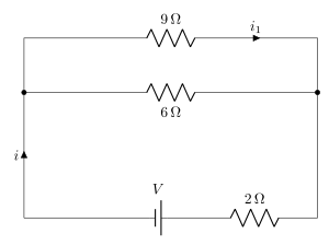
- AP EAPCET 2026Set ap-2026-05-19-FN1 markMCQQ.If power dissipated in the 9 Ω resistor in the circuit shown is 36 W, the potential difference across the 2 Ω resistor is [FIGURE] (a circuit with two parallel branches, a 9 Ω resistor carrying current i1 in the top branch and a 6 Ω resistor in the bottom branch, both branches joined at both ends; this parallel combination is connected in series with a battery of emf V and a 2 Ω resistor, with total current i flowing from the battery) (A) 2 volt (B) 4 volt (C) 8 volt (D) 10 volt
›Reveal solutionSolution
From P=i12R get i1=2A in the 9Ω; the parallel 6Ω carries 3A, so total i=5A and the 2Ω drops 10V.
Current in the 9Ω branch. Power dissipated is 36W:
P=i12R⇒36=i12(9)⇒i12=4⇒i1=2A.
Voltage across the parallel section. The voltage across the 9Ω resistor equals that across the parallel 6Ω resistor:
V∥=i1×9=2×9=18V.
Current in the 6Ω branch:
i2=618=3A.
Total current from the battery (this same current flows through the series 2Ω):
i=i1+i2=2+3=5A.
Potential difference across the 2Ω resistor:
V2Ω=i×2=5×2=10V.
✓Final answerThe potential difference across the 2Ω resistor is 10volt — option (D).
- AP EAPCET 2026Set ap-2026-05-20-FN1 markMCQQ.A resistor of resistance 30 Ω and a capacitor of reactance 40 Ω are connected in series to an ac supply. If the rms current through the resistor is 2 mA, then the wattless current is (A) zero (B) 2 mA (C) 1.2 mA (D) 1.6 mA
›Reveal solutionSolution
The wattless (idle) current component is the part of the total current that is out of phase with the voltage and does no net work — found using Isinϕ for a series RC circuit.
Concept and Intuition
In an AC circuit with both resistance and reactance, only the in-phase component of current (Icosϕ) contributes to real power dissipation. The out-of-phase (wattless/reactive) component is Isinϕ, where ϕ is the phase angle between voltage and current, determined by the ratio of reactance to impedance.
Step-by-Step Solution
- Impedance of the series RC circuit: Z=R2+XC2=302+402=900+1600=2500=50Ω.
- sinϕ=ZXC=5040=0.8.
- Wattless current =Isinϕ=2mA×0.8=1.6mA.
Common Mistakes
- Using cosϕ (which gives the power/wattful current, 1.2mA) instead of sinϕ for the wattless component.
- Forgetting that the resistor's current is the same as the total series current (they're in series), so no separate calculation is needed for "current through the resistor."
✓Final answerThe correct option is (D) — 1.6 mA.
ANSWER: D
- AP EAPCET 2025Set eng-2025-05-21-AN1 markMCQQ.The power dissipated by a uniform wire of resistance 100 Ω when a potential difference of 120 V is applied across its ends is (A) 122 W (B) 144 W (C) 160 W (D) 200 W
›Reveal solutionSolution
Tests the power–resistance relation P=V2/R for a fixed resistor; answer is 144 W.
Concept and Intuition
For a resistor with a fixed potential difference V across it, the power dissipated is entirely due to Joule heating, given by P=VI=I2R=RV2. Since we are given V and R directly, the most direct form to use is P=V2/R.
Step-by-Step Solution
- Given: R=100 Ω, V=120 V.
- Apply P=RV2=1001202=10014400.
- P=144 W.
Common Mistakes
- Confusing P=V2/R with P=VR or P=V/R (forgetting to square V).
- Arithmetic slip in dividing 14400 by 100.
✓Final answerThe correct option is (B) — 144 W.
ANSWER: B
- AP EAPCET 2025Set eng-2025-05-23-FN1 markMCQQ.A wire of resistance 'R' is bent in the form of a circular loop. Two points on the circle separated by a quarter circumference are connected to a battery of emf 'E' and negligible internal resistance. The heat generated in the wire per second is (A) 4RE2 (B) 3R16E2 (C) RE2 (D) 3R2E2
›Reveal solutionSolution
The wire loop splits into two resistive arcs in parallel between the battery terminals; combine them and use P=E2/Req.
Concept and Intuition
A uniform wire bent into a circle has resistance distributed uniformly along its length, so resistance of any arc is proportional to its arc length. When two points on the loop are tapped by a battery, current can flow to the other terminal via either arc — the two arcs are electrically in parallel, not in series, because both start and end at the same two nodes.
Step-by-Step Solution
- Total loop resistance is R, uniformly distributed, so resistance is proportional to arc length.
- A quarter-circumference arc has resistance R1=41R; the remaining three-quarters arc has resistance R2=43R.
- These two arcs connect the same pair of terminals, so they are in parallel:
Req=R1+R2R1R2=4R+43R(4R)(43R)=R163R2=163R
- Since the battery has negligible internal resistance, the full emf E appears across Req. The heat generated per second equals the electrical power delivered:
P=ReqE2=3R/16E2=3R16E2
Common Mistakes
- Treating the two arcs as being in series (adding to give the full R) instead of recognizing they share both endpoints and are in parallel.
- Forgetting that quarter-circumference splits the loop into a 1:3 length ratio, not two equal halves.
✓Final answerThe correct option is (B) — 3R16E2.
ANSWER: B
- AP EAPCET 2025Set ap-2025-05-20-FN1 markMCQQ.If an electric bulb is rated at 50 W for a 220 V ac supply, then the resistance of the bulb and the peak voltage of the ac source are respectively (A) 968 Ω,2202 V (B) 484 Ω,220 V (C) 968 Ω,220 V (D) 484 Ω,2202 V
›Reveal solutionSolution
The bulb's resistance follows from P=Vrms2/R, and the peak voltage is 2 times the rms (rated) voltage — giving 968Ω and 2202 V.
Concept and Intuition
An AC bulb's power rating (50 W at 220 V) refers to the rms voltage, since power dissipation in a resistor depends on rms values: P=RVrms2. Separately, any sinusoidal AC voltage has a peak value related to its rms value by V0=Vrms2, purely from the definition of rms for a sine wave — this is independent of the bulb's rating.
Step-by-Step Solution
- Resistance: R=PVrms2=50(220)2=5048400=968 Ω.
- Peak (maximum) voltage of the 220 V (rms) AC supply: V0=2×Vrms=2202 V.
- Combining: resistance =968 Ω, peak voltage =2202 V.
Common Mistakes
- Using V=220 directly as peak voltage instead of recognizing 220 V is the rms (rated) value.
- Computing R using V2/P but forgetting the rated 220 V is already rms, needlessly converting it first.
✓Final answerThe correct option is (A) — 968 Ω, 2202 V.
ANSWER: A
- AP EAPCET 2024Set eng-2024-05-21-FN1 markMCQQ.A lamp is rated at 240V, 60W. When in use the resistance of the filament of the lamp is 20 times that of cold filament. The resistance of the lamp when not in use is (A) 54 Ω (B) 60 Ω (C) 50 Ω (D) 48 Ω
›Reveal solutionSolution
Rated power and voltage give the filament's hot resistance; dividing by 20 gives the cold resistance.
Concept and Intuition
A lamp's "rated" values (240 V, 60 W) describe its operating (hot) state, since that's when it's glowing and consuming that power. The cold filament (before switch-on) has much lower resistance because resistivity of the metal filament increases sharply with temperature. The problem gives us the ratio between the two, so we first get the hot resistance from P=V2/R, then scale down.
Step-by-Step Solution
- Hot resistance: Rhot=PV2=60240×240=6057600=960 Ω.
- Given Rhot=20Rcold.
- Rcold=20Rhot=20960=48 Ω.
Common Mistakes
- Using P=I2R or P=VI without first finding I — the direct V2/P route avoids this.
- Multiplying by 20 instead of dividing (i.e. mixing up which resistance is bigger — hot is bigger since metals have positive temperature coefficient of resistance).
✓Final answerThe correct option is (D) — 48 Ω.
ANSWER: D
- AP EAPCET 2023Set ap-2023-05-23-AN1 markMCQQ.A resistor of 50Ω, an inductor and a capacitor are connected in series to an ac source of peak voltage 2002V. When the capacitor alone is removed from the circuit, the current lags the voltage by 37∘ and when the inductor alone is removed from the circuit, the current leads the voltage by 37∘. The power dissipated in the LCR circuit is (A) 400 W (B) 800 W (C) 200 W (D) 100 W
›Reveal solutionSolution
Equal-magnitude lag and lead angles show XL=XC, meaning the LCR circuit is at resonance; power dissipated is simply Vrms2/R=800 W.
Concept and Intuition
Removing the capacitor leaves an RL circuit (current lags voltage); removing the inductor leaves an RC circuit (current leads voltage). If both phase angles have the same magnitude (37∘), it means XL and XC individually produce the same magnitude of phase shift relative to R — i.e. XL=XC. That is exactly the resonance condition for the full LCR circuit, where the net reactance cancels and the circuit behaves purely resistively.
Step-by-Step Solution
- RL circuit (C removed): tan37∘=XL/R⇒XL=Rtan37∘=50×0.75=37.5Ω.
- RC circuit (L removed): tan37∘=XC/R⇒XC=50×0.75=37.5Ω.
- Since XL=XC, the full LCR circuit is at resonance: net reactance =0, impedance Z=R=50Ω.
- RMS voltage: Vrms=22002=200 V.
- Power dissipated =RVrms2=502002=5040000=800 W.
Common Mistakes
- Forgetting to convert the given peak voltage to RMS before computing power.
- Not recognizing that equal lag/lead angles imply XL=XC (resonance).
✓Final answerThe correct option is (B) — 800 W.
ANSWER: B
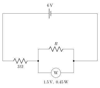
- AP EAPCET 2023Set eng-2023-05-16-FN1 markMCQQ.In the circuit given below, if the bulb is to glow with maximum intensity, the value of 'R' is (neglect internal resistance of the cell) [FIGURE] (a circuit diagram with a 6V battery at the top; below it the circuit splits into a branch with a 3Ω resistor in series with a resistor R, and this joins down to a bulb marked 'W' rated 1.5 V, 0.45 W, which connects back to complete the loop with the battery) (A) 1.25 Ω (B) 4.5 Ω (C) 6 Ω (D) 8.5 Ω
›Reveal solutionSolution
This tests using a bulb's rated voltage/power to find its rated current, then applying KVL and KCL to a series–parallel circuit to find the parallel resistor that makes the bulb operate exactly at its rated (maximum-intensity) point.
Concept and Intuition
A bulb glows with "maximum intensity" when it operates at its rated voltage and power — any brighter isn't achievable without exceeding its design rating. Here R and the bulb are in parallel (sharing the same voltage), and this combination is in series with the fixed 3Ω resistor and the ideal 6V battery. For the bulb to sit exactly at 1.5 V, the total current drawn from the battery is fixed by KVL, and R must draw whatever current is "left over" after the bulb takes its rated share.
Step-by-Step Solution
- Bulb rating: 1.5 V, 0.45 W ⇒ rated current Ibulb=VP=1.50.45=0.3 A.
- For maximum (rated) intensity, the voltage across the parallel section (bulb and R) must equal 1.5 V.
- Apply KVL around the loop: EMF = drop across 3Ω + drop across parallel section: 6=3Itotal+1.5.
- Solving: 3Itotal=4.5⇒Itotal=1.5 A.
- By KCL, current splits between the bulb and R: Itotal=Ibulb+IR⇒IR=1.5−0.3=1.2 A.
- Since R is in parallel with the bulb, it also has 1.5 V across it: R=IRV=1.21.5=1.25 Ω.
Common Mistakes
- Treating R, the 3Ω resistor, and the bulb as all in series (ignoring that R is in parallel with the bulb specifically).
- Forgetting to find the bulb's rated current from P=VI before doing the circuit analysis.
- Sign/arithmetic slip in the KVL equation, e.g. omitting the 1.5 V drop across the parallel section.
✓Final answerThe correct option is (A) — 1.25 Ω.
ANSWER: A
- AP EAPCET 2023Set eng-2023-05-17-AN1 markMCQQ.An inductor and a resistor of 25 Ω are connected in series to an ac source of voltage 100 sin (100 πt) volt. If the impedance of the circuit is 50 Ω, the average power dissipated per cycle in the circuit is (A) 10 W (B) 25 W (C) 50 W (D) 100 W
›Reveal solutionSolution
In a series LR AC circuit, average power is dissipated only in the resistor: P=Irms2R=50 W here.
Concept and Intuition
An ideal inductor stores and releases energy over a cycle without net dissipation — its current and voltage are 90° out of phase, so the average power delivered to it over a full cycle is zero. All the average power in an LR series circuit is therefore dissipated in the resistor, and it can be computed either from Irms2R or from VrmsIrmscosϕ (where cosϕ=R/Z is the power factor) — both give the same result.
Step-by-Step Solution
- Peak voltage from V=100sin(100πt): V0=100 V, so Vrms=V0/2=100/2 V.
- Given impedance Z=50 Ω, find Irms=Vrms/Z=50100/2=22=2 A.
- Average power is dissipated only in the resistor: P=Irms2R=(2)2×25=2×25=50 W.
- (Cross-check via power factor: cosϕ=R/Z=25/50=0.5; P=VrmsIrmscosϕ=2100×2×0.5=100×0.5=50 W — consistent.)
Common Mistakes
- Using peak voltage/current instead of rms values directly in the power formula.
- Forgetting that only the resistor dissipates average power in a pure L-R circuit (trying to also add an inductor "power" term).
✓Final answerThe correct option is (C) — 50 W.
ANSWER: C
- AP EAPCET 2022Set ap-2022-07-11-AN1 markMCQQ.10 W is to be delivered to a device via a wire having resistance 2 Ω. If 20 V is the voltage across the device, the power wasted in the process is (A) 3 W (B) 2 W (C) 0.5 W (D) 1.5 W
›Reveal solutionSolution
Finding the current from the device's power and voltage, then applying I2R to the wire, gives 0.5 W wasted.
Concept and Intuition
The same current flows through both the device and the connecting wire (they're in series). Knowing the power delivered to and the voltage across the device lets us find that current, which we then use to find the ohmic loss in the wire.
Step-by-Step Solution
- Current supplied to device: I=VP=20 V10 W=0.5 A.
- This same current flows through the 2 Ω wire.
- Power wasted (heat dissipated) in the wire: Pwire=I2R=(0.5)2(2)=0.5 W.
Common Mistakes
- Using the device's voltage (20 V) directly with the wire's resistance instead of first finding the actual current.
✓Final answerThe correct option is (C) — 0.5 W.
ANSWER: C
🎓Unlock everything free for 14 days
- ✓Full step-by-step solutions
- ✓Concept-first explanations
- ✓Methods, shortcuts & mistakes
- ✓PYQ mapping + timed mock tests
Full access for 14 days. No credit card required.