Q.Suppose the frequency of the source in the previous example can be varied.
🔒You're viewing a preview — the full solution, concept, methods & PYQ mapping are locked.
🔒 Start your 14-day free trial to unlock the full solution →Concept understanding — Resonance in AC Circuits
Resonance in AC Circuits
A series circuit containing a resistor R, an inductor L and a capacitor C driven by an AC source exhibits resonance — a sharp condition at which the circuit responds most strongly.
The Competing Reactances
In a series RLC circuit the inductor and capacitor oppose the current in opposite senses. Their reactances are
XL=ωL,XC=ωC1
where ω=2πf is the angular frequency. As frequency rises, XL grows while XC shrinks. The total impedance is
Z=R2+(XL−XC)2
The Resonance Condition
At one special frequency the two reactances become exactly equal and cancel:
XL=XC⇒ω0L=ω0C1⇒ω0=LC1
The corresponding resonant frequency is
f0=2πLC1
At this frequency the impedance falls to its minimum, Z=R (purely resistive), so the current reaches its maximum value
Imax=RVrms
Because the reactances cancel, the source voltage and current are exactly in phase — the power factor is 1 at resonance.
Physical Picture
At resonance energy sloshes back and forth entirely between the inductor's magnetic field and the capacitor's electric field, cycle after cycle. The source only has to make up the small amount of energy lost as heat in R. This is the electrical analogue of a swing pushed at its natural frequency: a small periodic drive builds a large oscillation.
Sharpness and the Q-factor
How sharply the current peaks around f0 is measured by the quality factor:
Q=Rω0L=R1CL
A large Q (small R) gives a tall, narrow resonance curve — the circuit is highly selective, responding to a very narrow band of frequencies. A small Q gives a broad, flat peak.
Why It Matters …
Why this formula?
Resonance in AC Circuits: Why the Key Formulas Hold
Resonance in an AC circuit occurs when the inductive reactance (XL) and capacitive reactance (XC) exactly cancel each other out. Let's build the understanding step-by-step.
1. The Core Condition for Resonance
Consider a series RLC circuit (resistor R, inductor L, capacitor C) driven by an AC voltage source V=V0sin(ωt).
The total impedance Z of the series combination is:
Z=R+j(XL−XC)
where:
- XL=ωL (inductive reactance)
- XC=ωC1 (capacitive reactance)
- j=−1
Why resonance happens:
The circuit "wants" to let maximum current flow. The opposition to current comes from both resistance and reactance. But reactance can be negative (capacitive) or positive (inductive). When they are equal in magnitude but opposite in sign, they cancel:
XL=XC
This is the fundamental condition — not a formula to memorize, but a logical consequence of impedance minimization.
2. Deriving the Resonant Frequency
From XL=XC:
ωL=ωC1
Multiply both sides by ω:
ω2LC=1
Thus:
ω0=LC1
Since ω=2πf, the resonant frequency in hertz is:
f0=2πLC1
Why this makes sense:
- A larger L or C means the circuit takes longer to "oscillate" — lower frequency.
- A smaller L or C means faster oscillations — higher frequency.
- The product LC controls the natural time scale of the circuit.
3. What Happens at Resonance — Key Consequences
(a) Impedance is Minimum (Purely Resistive)
At resonance, XL−XC=0, so:
Z=R+j(0)=R
Why: The reactive parts cancel, leaving only the resistance. The circuit behaves like a pure resistor.
(b) Current is Maximum
From Ohm's law for AC:
I=ZV
At resonance, Z=R (minimum possible), so current is maximum:
Imax=RV
Why: The opposition to current is smallest when reactance cancels.
(c) Voltage Across L and C Can Be Very Large
The voltage across the inductor:
VL=I⋅XL=RV⋅ω0L
The voltage across the capacitor:
VC=I⋅XC=RV⋅ω0C1
Since XL=XC at resonance, VL=VC in magnitude, but they are 180° out of phase — they cancel each other in the loop.
Why this is important:
If R is small, VL and VC can be many times larger than the source voltage V. This is called voltage magnification — a key concept for tuned circuits and filters.
--- …
Using the previous example's data: R=3 Ω, L=25.48 mH, C=796 μF, Vrms=200 V.
- Resonant frequency:
f0=2πLC1=2π(25.48×10⁻³)(796×10−6)1≈35.4 Hz
- At resonance the reactances cancel, so Z=R: Z=R=3 Ω,I=ZV=3200≈66.7 A …
With R=3 Ω, L=25.48 mH, C=796 μF and Vrms=200 V, resonance occurs at f0=2πLC1≈35.4 Hz, where Z=R=3 Ω, I=V/R≈66.7 A and P=V2/R≈13.3 kW.
At resonance the inductive and capacitive reactances of the series LCR circuit become equal and cancel, leaving a purely resistive impedance. This is where the impedance is smallest and the current is largest.
(a) Resonant frequency
Resonance requires XL=XC, i.e. ω0L=1/ω0C, giving ω0=1/LC and
f0=2πLC1
Substituting L=25.48×10⁻³ H and C=796×10−6 F:
LC=(25.48×10⁻³)(796×10−6)=2.03×10⁻⁵ s2,
LC=4.50×10⁻³ s,
f0=2π×4.50×10−31≈35.4 Hz.
(b) Impedance, current and power at resonance
Since XL=XC, the net reactance is zero and
Z=R2+(XL−XC)2=R=3 Ω.
The rms current is then maximum:
I=ZV=3200≈66.7 A. …
Method: Resonance Condition in Series RLC Circuit
This method applies when an AC source is connected to a series combination of a resistor (R), an inductor (L), and a capacitor (C). Resonance occurs when the inductive reactance equals the capacitive reactance.
Step 1 — Write the resonance condition
At resonance:
XL=XC
Where:
- XL=2πfL (inductive reactance)
- XC=2πfC1 (capacitive reactance)
Step 2 — Solve for resonant frequency f0
Set XL=XC:
2πf0L=2πf0C1
Multiply both sides:
(2πf0)2LC=1
Thus:
f0=2πLC1
Answer (a): The resonant frequency is f0=2πLC1
Step 3 — Impedance at resonance
At resonance, XL=XC, so they cancel each other. The total impedance is purely resistive:
Z=R
Impedance at resonance: Z=R
Step 4 — Current at resonance
Using Ohm’s law for AC circuits:
I=ZV=RV
Where V is the RMS voltage of the source.
Current at resonance: I=RV
Step 5 — Power dissipated at resonance …
Here are the common mistakes students make on resonance in AC circuits, along with how to avoid each — tailored for Indian exam accuracy (JEE, NEET, CBSE).
1. Using the Wrong Formula for Resonant Frequency
Mistake:
Students often confuse the formula for resonance in a series LCR circuit with that of a parallel circuit, or they forget the square root.
Correct formula (series LCR):
f0=2πLC1
How to avoid:
- Memorise: Resonance occurs when XL=XC.
- Derive quickly:
ωL=ωC1⇒ω2=LC1⇒f=2πLC1
- Never write f0=2π1CL — that’s wrong.
2. Forgetting That Impedance is Minimum (Not Maximum) at Resonance
Mistake:
Thinking Z is maximum at resonance (confusing with parallel resonance or voltage across L/C).
Correct:
At resonance, XL=XC, so:
Z=R2+(XL−XC)2=R
Impedance is minimum and purely resistive.
How to avoid:
- Remember: Resonance = minimum opposition to current.
- In a series circuit, current is maximum → impedance must be minimum.
3. Calculating Current Without Using the Correct Impedance
Mistake:
Using I=V/(XL−XC) or forgetting that Z=R at resonance.
Correct:
At resonance:
I0=RV
How to avoid:
- Always first find Z at resonance.
- If f=f0, then Z=R — no reactance left.
4. Power Dissipation Formula Error
Mistake:
Using P=VrmsIrmscosϕ but forgetting that at resonance cosϕ=1.
Correct:
At resonance, ϕ=0, so:
P=VrmsIrms=Irms2R
How to avoid:
- At resonance, circuit is purely resistive → power factor = 1.
- So P=Vrms2/R also works.
5. Mixing Up RMS and Peak Values
Mistake:
Using peak voltage V0 in formulas meant for RMS values, or vice versa.
Correct approach:
- If source voltage is given as V=V0sin(ωt), then Vrms=V0/2.
- Use RMS values for power and current calculations unless asked for peak.
How to avoid:
- Check the problem statement: “220 V” usually means RMS.
- Write explicitly:
Irms=RVrms
--- …
Showing the 12 most recent of 36 on this concept.
- AP EAPCET 2026Set eng-2026-05-12-AN1 markMCQQ.To have resonance in a LCR series circuit, the impedance (Z) value (A) Z>R (B) Z=R (C) Z<R (D) Z=0
›Reveal solutionSolution
At series resonance the reactances cancel exactly, so the impedance equals the pure resistance: Z=R.
Concept and Intuition
In a series LCR circuit, impedance is Z=R2+(XL−XC)2. Resonance is defined precisely as the condition where the inductive and capacitive reactances are equal in magnitude and opposite in phase effect, so they cancel each other in the impedance expression, leaving only the resistive part.
Step-by-Step Solution
- Impedance of a series LCR circuit: Z=R2+(XL−XC)2.
- At resonance, by definition, XL=XC.
- Substituting: Z=R2+02=R.
Common Mistakes …
- AP EAPCET 2026Set eng-2026-05-13-FN1 markMCQQ.In the given circuit, the readings of voltmeters V1 and V2 are 300 V each. The reading of voltmeter V3 and ammeter A are respectively: [FIGURE - a series circuit with an inductor L, a capacitor C, and a resistor R=100 Ω connected in series; a voltmeter V1 is connected across L, V2 across C, and V3 across R; an ammeter A is in series with the circuit; the circuit is powered by an AC source of 220 V, 50 Hz] (A) 100 V, 2.0 A (B) 150 V, 2.2 A (C) 220 V, 2.0 A (D) 220 V, 2.2 A
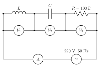
›Reveal solutionSolution
Equal VL and VC readings cancel in the series-LCR phasor sum, so the resistor takes the full 220 V source voltage, giving I=2.2 A.
Concept and Intuition
In a series LCR circuit, the voltages across L and C are always 180° out of phase with each other (they point in opposite directions on the phasor diagram), while the resistor voltage is in phase with the current and perpendicular to both. The source voltage is the phasor sum:
V=(VL−VC)2+VR2.
When VL=VC (as given, both 300 V), the reactive terms cancel completely, leaving V=VR. This is exactly the condition of resonance-like behaviour — even though VL and VC individually can be much larger than the source voltage, they cancel each other out, and the resistor "sees" the entire applied EMF.
Step-by-Step Solution
- Given V1=VL=300 V, V2=VC=300 V, source =220 V (rms).
- Phasor relation: Vsource=(VL−VC)2+VR2.
- Since VL=VC, (VL−VC)=0, so Vsource=VR.
- Hence V3=VR=220 V (matching the given source voltage, consistent — this is the resonance condition). …
- AP EAPCET 2026Set eng-2026-05-14-FN1 markMCQQ.To have dissipative power in a LCR series circuit to be half (A) current amplitude =2× (Maximum current amplitude) (B) current amplitude =2(Maximum current amplitude) (C) current amplitude =(Maximum current amplitude)21 (D) current amplitude =2(Maximum current amplitude)
›Reveal solutionSolution
This tests the half-power point condition in a driven LCR series circuit, central to defining bandwidth and quality factor. Answer: current amplitude =2I0,max.
Concept and Intuition
In a series LCR circuit driven at varying frequency, the current amplitude I0(ω) peaks at resonance (I0,max) and falls off away from resonance. Since the power dissipated depends on the square of the current amplitude, halving the power does not mean halving the current — it means reducing the current amplitude by a factor of 2 (because squaring 1/2 gives 1/2). This is exactly the condition used to define the 'half-power frequencies' that set the resonance bandwidth.
Step-by-Step Solution
- Power dissipated for a given current amplitude: P∝I02 (with everything else, e.g. the resistance, held fixed for the comparison).
- Maximum power (at resonance): Pmax∝I0,max2.
- We want P=2Pmax: I02=2I0,max2.
- Taking the square root: I0=2I0,max.
Common Mistakes …
- AP EAPCET 2026Set eng-2026-05-13-AN1 markMCQQ.In the figure shown, three ac voltmeters are connected. At resonance, [FIGURE: an ac source connected in series to a resistor R, an inductor L, and a capacitor C; voltmeter V1 is connected across R; voltmeter V2 is connected across the series combination of L and C; voltmeter V3 is connected across the same L-C combination on the source side] (A) V2=0 (B) V1=0 (C) V3=0 (D) V3=V2=0
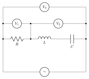
›Reveal solutionSolution
This is a series RLC resonance question read from the figure: V1 is across R, V2 is across the L–C series combination, and V3 is across the whole branch. At resonance XL=XC, so the L and C voltages cancel exactly — meaning V2=0.
Concept and Intuition
In a series RLC circuit, the current I is common to all elements. The voltage across the inductor leads the current by 90°, while the voltage across the capacitor lags it by 90° — so VL and VC are exactly 180° out of phase with each other. At resonance, XL=XC, so VL=IXL and VC=IXC have equal magnitude too. Two phasors of equal magnitude, opposite in phase, sum to zero.
Step-by-Step Solution
- At resonance, ωL=ωC1⇒XL=XC.
- VL=IXL and VC=IXC are equal in magnitude.
- Since VL leads I by 90° and VC lags I by 90°, they are anti-phase to each other; their phasor sum V2=VL+VC=0. …
- AP EAPCET 2026Set eng-2026-05-15-AN1 markMCQQ.In a series LCR circuit the resistance, inductive reactance and capacitive reactance are in the ratio 3 : 8 : 4. If the potential difference across the resistor is 12 V, then the emf of the ac source used in the circuit is (A) 48 V (B) 16 V (C) 180 V (D) 20 V
›Reveal solutionSolution
Recognizing the 3-4-5 impedance triangle hidden in the given ratio gives an emf of 20 V.
Concept and Intuition
In a series LCR circuit, VR=IR, VL=IXL, VC=IXC all share the same current I, so the given ratio R:XL:XC=3:8:4 is also the ratio VR:VL:VC. The net reactive voltage is VL−VC (they oppose each other, 180° out of phase), and the source emf is the phasor sum ε=VR2+(VL−VC)2.
Step-by-Step Solution
- Let R=3k, XL=8k, XC=4k for some common constant k.
- Current I=RVR=3k12=k4.
- Net reactance X=XL−XC=4k, so the net reactive voltage =IX=k4×4k=16 V.
- Impedance Z=R2+X2=(3k)2+(4k)2=5k — a 3-4-5 triangle. …
- AP EAPCET 2026Set ap-2026-05-19-FN1 markMCQQ.A series LCR circuit with R=40 Ω, L=3 H and C=20 μF is connected to a 400 V ac supply with variable frequency. When the frequency of supply equals to natural frequency of the circuit, the average power transferred to the circuit in one complete cycle is (A) 200 W (B) 4000 W (C) 6000 W (D) 800 W
›Reveal solutionSolution
Tests power dissipation in a series LCR circuit at resonance, where the reactive elements cancel and the circuit behaves as a pure resistor.
Concept and Intuition
At resonance, the inductor's reactance XL=ωL exactly equals the capacitor's reactance XC=ωC1, and since they act with opposite phase in a series circuit, their effects cancel completely. The circuit's impedance collapses to just R, current and voltage are in phase, and the power dissipated is the same as it would be for a plain resistor connected directly to the same supply — no need to even compute L or C numerically for the power itself (they only matter for finding the resonant frequency, not the power at it).
Step-by-Step Solution
- Resonance condition: ω0=LC1, at which XL=XC.
- Impedance at resonance: Z=R2+(XL−XC)2=R2+0=R=40Ω.
- At resonance, current and voltage are in phase (power factor cosϕ=1), so average power =VrmsIrmscosϕ=VrmsIrms=ZVrms2=RVrms2. …
- AP EAPCET 2026Set ap-2026-05-20-AN1 markMCQQ.Match the following, if XL and XC are inductive and capacitive reactances respectively List I | List II A. XL=XC | I. Current in phase with voltage B. XL<XC | II. Current lags behind voltage C. XL>XC | III. Current leads voltage (A) A – II, B – III, C – I (B) A – III, B – II, C – I (C) A – III, B – I, C – II (D) A – I, B – III, C – II
›Reveal solutionSolution
In a series LCR circuit, comparing XL and XC tells you whether the circuit behaves inductively (current lags) capacitively (current leads) or resistively at resonance (current in phase); this gives A–I, B–III, C–II.
Concept and Intuition
In an AC series LCR circuit, the phase angle ϕ between current and voltage is given by tanϕ=RXL−XC.
- If XL=XC, ϕ=0: this is resonance, and the circuit is purely resistive — current and voltage are in phase.
- If XL<XC, ϕ<0: the circuit is net capacitive, and in a capacitive circuit current leads the applied voltage.
- If XL>XC, ϕ>0: the circuit is net inductive, and current lags behind the voltage.
Step-by-Step Solution
- Recall tanϕ=(XL−XC)/R.
- XL=XC⇒ϕ=0⇒ current in phase with voltage ⇒ matches item I.
- XL<XC⇒ϕ<0⇒ voltage lags current, i.e. current leads voltage ⇒ item III. …
- AP EAPCET 2025Set eng-2025-05-21-FN1 markMCQQ.The resonant frequency of an LC circuit is f0. If a dielectric slab of constant 16 is inserted completely between the plates of the capacitor, then the resonant frequency is (A) 2f0 (B) 2f0 (C) 4f0 (D) 4f0
›Reveal solutionSolution
This tests how the resonant frequency of an LC circuit changes when the capacitor's dielectric is changed. Answer: 4f0.
Concept and Intuition
The resonant frequency of an LC circuit depends on both L and C as f0∝LC1. Filling the capacitor's gap with a dielectric multiplies its capacitance by the dielectric constant K (with L unaffected), so the new frequency scales as K1 times the original.
Step-by-Step Solution
- f0=2πLC1.
- Dielectric constant K=16 inserted completely: C′=16C. …
- AP EAPCET 2025Set eng-2025-05-21-AN1 markMCQQ.In an LCR series circuit, if the potential differences across inductor, capacitor and resistor are 60 V, 30 V and 40 V respectively, then the ac voltage applied to the circuit is (A) 50 V (B) 70 V (C) 130 V (D) 60 V
›Reveal solutionSolution
In a series LCR circuit the voltages across L, C, R combine via a phasor (not scalar) sum; the applied voltage works out to 50 V.
Concept and Intuition
In a series LCR AC circuit, the same current flows through all elements, but the voltage across the resistor is in phase with the current, while the voltage across the inductor leads by 90∘ and across the capacitor lags by 90∘. So VL and VC are antiparallel to each other and both perpendicular to VR on a phasor diagram. The net applied voltage is the phasor sum: V=VR2+(VL−VC)2.
Step-by-Step Solution
- Given: VL=60 V, VC=30 V, VR=40 V.
- Net reactive voltage: VL−VC=60−30=30 V. …
- AP EAPCET 2025Set eng-2025-05-22-FN1 markMCQQ.For better tuning of a series LCR circuit in a communication system, the preferred combination is (A) R=20 Ω; L=15 H; C=35 μF (B) R=15 Ω; L=40 H; C=20 μF (C) R=25 Ω; L=15 H; C=45 μF (D) R=15 Ω; L=20 H; C=45 μF
›Reveal solutionSolution
Tuning sharpness in a series LCR circuit is governed by its quality factor Q=R1L/C; the combination with the smallest R, largest L, and smallest C gives by far the largest Q, hence the best tuning.
Concept and Intuition
A series LCR circuit used for tuning (e.g. selecting one radio station out of many nearby frequencies) needs a sharp resonance peak — a large response at the resonant frequency and rapidly falling response away from it. The sharpness of resonance is quantified by the quality factor Q=Rω0L=R1CL. Physically: low resistance R means less energy dissipated per cycle (less damping); a large L (relative to C) means the reactive energy sloshing between the inductor and capacitor is large compared to what's lost in R each cycle. All of these push Q up, meaning "better tuning" corresponds to small R, large L, and small C together — not any one factor alone, which is why we must compute Q for each option rather than eyeball individual values.
Step-by-Step Solution
- Formula: Q=R1CL.
- Option (A): R=20, L=15, C=35μF: L/C=15/35×10−6=4.286×105; ⋅≈654.7; Q≈654.7/20≈32.7.
- Option (B): R=15, L=40, C=20μF: L/C=40/20×10−6=2×106; ⋅≈1414.2; Q≈1414.2/15≈94.3.
- Option (C): R=25, L=15, C=45μF: L/C=15/45×10−6=3.333×105; ⋅≈577.4; Q≈577.4/25≈23.1. …
- AP EAPCET 2025Set eng-2025-05-23-FN1 markMCQQ.If a resistor of resistance 4 Ω, a capacitor of capacitive reactance 6 Ω and an inductor of inductive reactance 9 Ω are connected in series with an ac source, then the impedance of the circuit is (A) 19 Ω (B) 11 Ω (C) 7 Ω (D) 5 Ω
›Reveal solutionSolution
For a series R-L-C circuit, only the net reactance (the difference between inductive and capacitive reactance) combines with resistance in quadrature to give the impedance.
Concept and Intuition
In a series AC circuit, the voltage across the inductor and the voltage across the capacitor are 180° out of phase with each other (both being 90° out of phase with the current, but in opposite senses). So their reactances partially cancel rather than add: the net reactance is X=XL−XC. The resistor's voltage is in phase with the current, 90° out of phase with the net reactive voltage, so resistance and net reactance combine as the two legs of a right triangle to give the impedance.
Step-by-Step Solution
- Given: R=4Ω, XC=6Ω, XL=9Ω.
- Net reactance: X=XL−XC=9−6=3Ω. …
- AP EAPCET 2025Set ap-2025-05-20-AN1 markMCQQ.A 100Ω resistor, a 50μF capacitor and an inductor are connected in series to an ac source of frequency 50 Hz. If the circuit is in resonance, then the impedance of the circuit is (A) 100Ω (B) 200Ω (C) 180Ω (D) 250Ω
›Reveal solutionSolution
At resonance in a series RLC circuit, the reactive parts cancel and the circuit behaves purely resistively, so impedance equals R.
Concept and Intuition
In a series RLC circuit, impedance is Z=R2+(XL−XC)2. At resonance, XL=XC by definition, so the reactive term vanishes entirely, leaving only R.
Step-by-Step Solution
- At resonance: XL=XC.
- Z=R2+(XL−XC)2=R2+0=R. …
🎓Unlock everything free for 14 days
- ✓Full step-by-step solutions
- ✓Concept-first explanations
- ✓Methods, shortcuts & mistakes
- ✓PYQ mapping + timed mock tests
Full access for 14 days. No credit card required.