Q.A 44 mH inductor is connected to 220 V, 50 Hz ac supply. Determine the rms value of the current in the circuit.
Concept understanding — Inductive Reactance Change
Inductive Reactance Change – A First Look
Imagine you're pushing a child on a swing. If you push at just the right moment — when the swing is coming back toward you — each push adds energy and the swing goes higher. But if you push at random moments, sometimes you push against the swing's motion, and it barely moves. The swing "resists" being pushed at the wrong time.
An inductor in an AC circuit behaves exactly like that swing. It doesn't resist current the way a resistor does (by turning energy into heat). Instead, it resists changes in current — and the faster the current tries to change, the more the inductor pushes back.
The Core Intuition
An inductor is just a coil of wire. When current flows through it, it creates a magnetic field. If the current tries to change — say, increase or decrease — the magnetic field changes too. That changing field induces a voltage in the coil that opposes the change in current. This is Lenz's law in action: the induced voltage always fights the change that caused it.
So the inductor acts like a kind of "inertia" for current. The more rapidly the current tries to change, the stronger the opposition. In a DC circuit, once the current settles to a steady value, the inductor stops opposing — it becomes just a wire. But in an AC circuit, the current is always changing direction, so the inductor is always fighting.
The Precise Statement
Inductive reactance (XL) is the opposition an inductor offers to alternating current. It depends on two things:
- The inductance L of the coil (measured in henries, H) — bigger coil, more opposition.
- The frequency f of the AC supply (measured in hertz, Hz) — faster changes, more opposition.
The formula is:
XL=2πfL
Where:
- XL is in ohms (Ω)
- f is the frequency in Hz
- L is the inductance in H
Key point: Unlike resistance, which is constant for a given resistor, inductive reactance changes with frequency. Double the frequency, double the reactance. Halve the frequency, halve the reactance.
What "Inductive Reactance Change" Means
When we talk about "inductive reactance change," we mean: how XL varies when either the frequency or the inductance changes.
| Change | Effect on XL | Why? |
|---|---|---|
| Frequency increases | XL increases | Current changes faster → stronger opposition |
| Frequency decreases | XL decreases | Current changes slower → weaker opposition |
| Inductance increases | XL increases | More magnetic field → more opposition |
| Inductance decreases | XL decreases | Less magnetic field → less opposition |
A common mistake is to think inductive reactance behaves like resistance. It doesn't. Resistance dissipates energy as heat; reactance stores and releases energy in the magnetic field. Also, reactance depends on frequency — resistance usually doesn't.
A Simple Example
Suppose you have a coil with L=0.1 H connected to a 50 Hz AC supply.
XL=2π(50)(0.1)=2π(5)=10π≈31.4 Ω
Now change the frequency to 100 Hz:
XL=2π(100)(0.1)=2π(10)=20π≈62.8 Ω
The reactance doubled because the frequency doubled. The inductor "fights" harder at higher frequencies.
Why This Matters
In AC circuits, inductive reactance is why:
- Inductors block high-frequency signals (like in filters)
- Motors and transformers behave differently at different frequencies
- Power systems must account for reactance to avoid voltage drops
Think of XL as a "frequency-dependent resistor" — but remember, it doesn't waste power. It just stores and returns energy each cycle.
So when you hear "inductive reactance change," you now know: it's simply how the opposition of an inductor to AC varies with frequency or inductance. The formula XL=2πfL is your anchor — everything else follows from it.
Inductive reactance and how it varies with frequency, X_L = 2πfL, is a core formula from the NCERT Class 12 Physics chapter on alternating current, tested regularly in CBSE boards and JEE Main. Students searching "inductive reactance formula and frequency dependence class 12 physics" will find this frequency-versus-reactance table matches exactly what NCERT-aligned numericals expect.
Why this formula?
Inductive Reactance Change: Why the Formula Holds
Let's build this from first principles — understanding why inductive reactance behaves as it does, not just memorizing XL=2πfL.
1. The Core Idea: Opposition to Current Change
An inductor doesn't "resist" current like a resistor. Instead, it opposes changes in current due to self-induction.
- When current changes, the magnetic flux through the inductor changes.
- By Faraday's Law, a changing flux induces an emf (voltage) that opposes the change — this is Lenz's Law.
- The induced voltage is proportional to the rate of change of current:
vL=Ldtdi
Where:
- vL = induced voltage across inductor (V)
- L = inductance (henry, H)
- dtdi = rate of change of current (A/s)
2. Applying a Sinusoidal Current
In AC circuits, current is sinusoidal. Let:
i(t)=Imsin(ωt)
Where:
- Im = peak current (A)
- ω=2πf = angular frequency (rad/s)
- f = frequency (Hz)
Now compute the induced voltage:
vL=Ldtd[Imsin(ωt)]=L⋅Im⋅ωcos(ωt)
So:
vL=ωLImcos(ωt)
3. The Phase Shift: Voltage Leads Current
Notice:
- Current: sin(ωt)
- Voltage: cos(ωt)=sin(ωt+90∘)
Voltage leads current by 90∘ (or π/2 radians). This is a key property — the inductor causes a phase difference.
4. Defining Inductive Reactance
Reactance is the ratio of peak voltage to peak current (magnitude only, ignoring phase):
From above:
- Peak voltage: Vm=ωLIm
- Peak current: Im
Thus:
XL=ImVm=ωL
Since ω=2πf:
XL=2πfL
Where XL is in ohms (Ω).
5. Why It Changes with Frequency
The formula reveals the why:
- Higher frequency (f increases) → dtdi is larger for the same current amplitude → larger induced voltage → greater opposition → XL increases.
- Lower frequency (f decreases) → slower current change → smaller induced voltage → less opposition → XL decreases.
- DC (f=0) → dtdi=0 → no induced voltage → XL=0 (inductor acts as a short circuit).
6. Summary of Key Insights
| Aspect | Explanation |
|---|---|
| Origin | Faraday's Law + Lenz's Law: changing current induces opposing voltage |
| Formula | XL=2πfL |
| Frequency dependence | XL∝f — higher frequency, more opposition |
| Phase | Voltage leads current by 90∘ |
| DC behavior | XL=0 at f=0 (steady current) |
7. Exam-Relevant Takeaway
Inductive reactance is not a resistance — it's a frequency-dependent opposition arising from electromagnetic induction. The formula XL=2πfL is a direct consequence of vL=Ldtdi applied to sinusoidal signals.
Always remember: the inductor opposes change, and the faster the change (higher f), the stronger the opposition.
The key idea is that in a purely inductive AC circuit, the current lags the voltage by 90∘ and the opposition to current is given by inductive reactance XL, not resistance.
Step 1: Compute the inductive reactance.
XL=2πfL=2π×50×44×10−3
XL=2π×2.2≈13.82 Ω
Step 2: Apply Ohm's law for an AC circuit. For a pure inductor, the rms current is the rms voltage divided by the inductive reactance.
Irms=XLVrms=13.82220
Step 3: Calculate the result.
Irms≈15.92 A
The rms value of the current is 15.92 A.
For a pure inductor in an AC circuit, the current lags the voltage by 90∘ and its rms value is given by Irms=Vrms/XL, where XL=2πfL. Here, Irms≈15.9 A.
Why This Works — The Concept
When you connect an inductor to an AC supply, something interesting happens. Unlike a resistor, an inductor doesn't just "resist" current — it opposes changes in current. This opposition is called inductive reactance (XL), and it depends on both the frequency of the supply and the inductance itself.
The key idea: For a pure inductor (no resistance), the voltage and current are out of phase by exactly 90∘, with the current lagging behind the voltage. But for calculating the magnitude of the current (the rms value), we can treat the inductor just like a resistor — using Ohm's law for AC circuits:
Irms=XLVrms
where XL=2πfL is the inductive reactance in ohms.
The beauty is that rms values follow the same arithmetic as DC values, as long as we use the correct "resistance" (reactance) for the component.
Step-by-Step Solution
1. Identify the given quantities
We have:
- Inductance, L=44 mH=44×10−3 H
- Supply voltage (rms), Vrms=220 V
- Frequency, f=50 Hz
A common mistake is forgetting to convert millihenries to henries. 44 mH is 0.044 H, not 44 H!
2. Calculate the inductive reactance
The inductive reactance tells us how much the inductor "resists" the AC current:
XL=2πfL
Substitute the values:
XL=2π×50×44×10−3
XL=2π×50×0.044
XL=2π×2.2
XL=4.4π Ω
If you want a numerical value: XL≈4.4×3.1416≈13.82 Ω
3. Apply Ohm's law for AC circuits
For a pure inductor, the rms current is simply:
Irms=XLVrms
Irms=4.4π220
Simplify: 220/4.4=50, so:
Irms=π50 A
4. Get the numerical value
Irms=3.141650≈15.92 A
Notice that 50/π is an exact expression. In many exam problems, leaving the answer in terms of π is perfectly acceptable — and often preferred. The numerical approximation is 15.9 A.
Why No Phase Angle in the Answer?
You might wonder: shouldn't we account for the 90∘ phase difference? The answer is no — because the question specifically asks for the rms value of the current. RMS values are magnitudes only; they don't carry phase information. The phase angle matters when you're combining components or calculating instantaneous power, but for a single inductor's current magnitude, it's just Vrms/XL.
In a purely inductive circuit, the current lags voltage by 90∘, but the rms magnitude follows Irms=Vrms/XL — exactly like Ohm's law.
The rms value of the current is π50 A≈15.9 A.
Method: Inductive Reactance & Ohm’s Law for AC Circuits
This method uses the concept that an ideal inductor opposes AC current through inductive reactance (XL), which behaves like resistance in Ohm’s law for AC circuits.
Steps
Step 1: Recall the formula for inductive reactance
XL=2πfL
where:
- f = frequency in Hz
- L = inductance in henry (H)
Step 2: Convert units and substitute values
Given:
- L=44 mH=44×10−3 H
- f=50 Hz
- Vrms=220 V
XL=2π(50)(44×10−3)
XL=2π(2.2)
XL=4.4π Ω
Step 3: Apply Ohm’s law for AC circuits
For a purely inductive circuit:
Irms=XLVrms
Irms=4.4π220
Irms=π50
Step 4: Compute the numerical value
Irms=3.141650≈15.92 A
Final Answer
Irms≈15.92 A
Key Concept Check
- The inductor does not dissipate power (ideal case) — it only stores and returns energy.
- The current lags the voltage by 90∘ in a pure inductor.
- The opposition is reactance (XL), not resistance — hence no power dissipation, only reactive power.
Here are the common mistakes students make when solving this exact problem, along with how to avoid each one.
Mistake 1: Forgetting to Convert Inductance to Henry
The mistake:
Students see 44 mH and plug in 44 directly into the formula, forgetting the milli prefix.
Why it happens:
The formula XL=2πfL expects L in henry (H), not millihenry.
How to avoid:
Always write the conversion step explicitly:
L=44 mH=44×10−3 H=0.044 H
Mistake 2: Using the Wrong Formula for Impedance
The mistake:
Students treat the inductor like a resistor and write I=V/R, using R instead of XL.
Why it happens:
They confuse resistive circuits with inductive AC circuits.
How to avoid:
Remember: For a pure inductor, there is no resistance — only inductive reactance:
XL=2πfL
Then use Ohm’s law for AC:
Irms=XLVrms
Mistake 3: Using Peak Voltage Instead of RMS Voltage
The mistake:
Students take 220 V as peak voltage and use V0 in the formula.
Why it happens:
They forget that the problem explicitly says "220 V, 50 Hz ac supply" — this is the rms value by convention in Indian exams.
How to avoid:
In AC circuit problems, unless stated as "peak voltage" or "V0", assume the given voltage is rms.
Here:
Vrms=220 V
Mistake 4: Forgetting the Factor of 2π in XL
The mistake:
Students write XL=fL or XL=πfL, missing the 2.
Why it happens:
They memorise the formula incorrectly.
How to avoid:
Write the full formula every time:
XL=2πfL
And remember: π≈3.14, so 2π≈6.28.
Mistake 5: Calculation Errors with π
The mistake:
Using π=3.14 but making arithmetic mistakes, or rounding too early.
How to avoid:
Do the calculation step-by-step:
- XL=2×3.14×50×0.044
- First: 2×50=100
- Then: 100×0.044=4.4
- Finally: 4.4×3.14=13.816 Ω
Then:
Irms=13.816220≈15.92 A
Final answer: 15.92 A (or approximately 16 A)
Quick Checklist to Avoid All Mistakes
- Convert mH → H (×10−3)
- Use XL=2πfL, not R
- Use Vrms=220 V (not peak)
- Include 2π, not just π or fL
- Do arithmetic carefully, avoid early rounding
Master these, and you’ll never lose marks on this problem again.
Showing the 12 most recent of 13 on this concept.
- AP EAPCET 2026Set eng-2026-05-18-FN1 markMCQQ.The ratio of the turns per unit length in two inductors is 2 : 1. Then the ratio of the impedances produced by the inductors is (A) 2 (B) 4 (C) 21 (D) 41
›Reveal solutionSolution
Inductance (and hence inductive impedance at fixed frequency) scales as the square of the turn density. Answer: 4.
Concept and Intuition
For a solenoid-type inductor, L=μ0n2Al, where n=N/l is the number of turns per unit length. This comes from B=μ0nI inside the coil combined with flux linkage through all N=nl turns — the n appears twice (once from the field, once from the number of turns linking that field), giving the n2 dependence. Since inductive reactance XL=ωL at a fixed angular frequency ω, the impedance ratio mirrors the inductance ratio.
Step-by-Step Solution
- L∝n2 (for identical core, area, and length).
- Z=XL=ωL∝n2 (same ω for both).
- Given n1:n2=2:1, so Z2Z1=(n2n1)2=22=4.
Common Mistakes
- Treating L (and Z) as directly proportional to n instead of n2.
- Confusing turns-per-unit-length ratio with total-turns ratio (they're the same here since it's a ratio, but easy to conflate the concepts).
✓Final answerThe correct option is (B) — 4.
ANSWER: B
- AP EAPCET 2025Set eng-2025-05-22-AN1 markMCQQ.A resistor of 450 Ω and an inductor are connected in series to an ac source of frequency π75 Hz. If the power factor of the circuit is 0.6, then the inductance connected in the circuit is (A) 6 mH (B) 4 H (C) 4 mH (D) 6 H
›Reveal solutionSolution
This tests series RL ac-circuit relations: power factor gives impedance, impedance gives reactance, and reactance gives inductance. The answer is L=4 H.
Concept and Intuition
In a series RL circuit, the resistor and inductor's voltage phasors are perpendicular (resistor voltage in phase with current, inductor voltage 90∘ ahead), so the impedance triangle has R as the base and XL as the perpendicular side, with Z the hypotenuse. The power factor cosϕ=R/Z tells us how "resistive" the circuit looks overall; once we know cosϕ and R, geometry pins down Z and hence XL, and dividing XL by the angular frequency gives L.
Step-by-Step Solution
- Power factor: cosϕ=ZR=0.6⇒Z=0.6R=0.6450=750 Ω.
- Impedance relation: Z2=R2+XL2⇒XL=Z2−R2=7502−4502.
7502=562500,4502=202500,XL=360000=600 Ω
- Angular frequency: ω=2πf=2π×π75=150 rads−1.
- Inductance: XL=ωL⇒L=ωXL=150600=4 H.
Common Mistakes
- Using f directly instead of ω=2πf when relating XL and L.
- Sign/root errors when computing 7502−4502 (it factors nicely as (750−450)(750+450)=300×1200=360000=600).
✓Final answerThe correct option is (B) — 4 H.
ANSWER: B
- AP EAPCET 2025Set ap-2025-05-19-FN1 markMCQQ.If an inductor of inductance 0.5 μH is connected to an ac source of frequency 70 MHz and voltage 3.3 V, then the current through the inductor is (A) 5 mA (B) 7.5 mA (C) 15 mA (D) 30 mA
›Reveal solutionSolution
The inductive reactance XL=2πfL at 70MHz for a 0.5μH inductor works out to about 220Ω; dividing the given voltage by this reactance gives a current of 15mA.
Concept and Intuition
An ideal inductor connected to an AC source opposes the current with an impedance called inductive reactance, XL=ωL=2πfL, which increases with frequency. The current amplitude (or rms current, matching whichever the voltage is quoted as) is then simply Ohm's-law-like: I=V/XL.
Step-by-Step Solution
- XL=2πfL=2π×(70×106Hz)×(0.5×10⁻⁶H).
- fL=70×106×0.5×10−6=35.
- XL=2π×35≈219.9Ω.
- I=XLV=219.93.3≈0.015A=15mA.
Common Mistakes
- Forgetting the factor of 2π when converting frequency to angular frequency.
- Unit slip between μH and H, or between MHz and Hz.
✓Final answerThe correct option is (C) — 15 mA.
ANSWER: C
- AP EAPCET 2024Set eng-2024-05-18-FN1 markMCQQ.In the figure, if A & B are identical bulbs, which bulb glows brighter [FIGURE] (an AC circuit with two parallel branches between a common pair of rails, one branch containing a 100 mH inductor in series with bulb A, the other branch containing a 10 pF capacitor in series with bulb B; both branches are connected across an AC source) (A) A (B) B (C) Both with equal brightness (D) Both do not glow
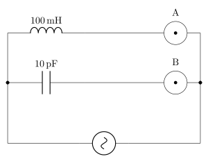
›Reveal solutionSolution
The brightness of each bulb depends on the current through it, which is determined by the impedance of its branch at the AC source frequency. Since the inductor and capacitor have opposite frequency-dependent reactances, one branch will have much lower impedance than the other, making one bulb glow brighter. The correct option is (A).
-
Understand the circuit and the goal
Bulbs A and B are identical, so their brightness is directly proportional to the power dissipated, which depends on the square of the current through them. The two branches are in parallel across the same AC source. The current in each branch is limited by the total impedance of that branch:
- Branch A: inductor (100 mH) in series with bulb A.
- Branch B: capacitor (10 pF) in series with bulb B. The bulbs themselves have some resistance R (same for both). The source is AC, but its frequency is not given — this is the key puzzle.
-
Recall the frequency dependence of reactances
- Inductive reactance: XL=2πfL — increases with frequency.
- Capacitive reactance: XC=2πfC1 — decreases with frequency. For a typical AC mains frequency (e.g., 50 Hz or 60 Hz), let’s see what happens.
-
Estimate the reactances at a typical mains frequency
Take f=50Hz (common in many countries).
- L=100mH=0.1H
XL=2π(50)(0.1)=10π≈31.4Ω
- C=10pF=10×10−12F
XC=2π(50)(10×10−12)1=2π×5×10−101≈3.14×10−91≈3.18×10⁸Ω
That’s 318 million ohms — an enormous impedance. Even if the bulb’s resistance is, say, 100 Ω, the capacitor branch is essentially an open circuit.
-
Compare the branch impedances
- Branch A impedance: ZA=R2+XL2. With XL≈31.4Ω and R maybe 100 Ω, ZA is on the order of 100–200 Ω.
- Branch B impedance: ZB=R2+XC2≈XC (since XC is huge), so ZB≈3×10⁸Ω. The current in branch B is therefore microscopic compared to branch A. Bulb B will not glow at all, while bulb A glows normally.
-
What if the frequency is extremely high?
If the source were at a very high frequency (e.g., radio frequencies), XL would become large and XC small, possibly reversing the situation. But the problem is from a typical physics exam context, where the AC source is assumed to be standard mains (50/60 Hz). No special frequency is mentioned, so we assume ordinary conditions.
-
Check the possibility of resonance
The two branches are in parallel, but there is no single LC tank — each branch has its own reactive component. The bulbs are in series with each reactive element, so the circuit is not a parallel resonant circuit that could equalize currents. Even if the source frequency were such that XL=XC, the currents would still differ because the branches are independent parallel paths; the branch with the smaller impedance draws more current.
Watch outA common mistake is to think that because the inductor and capacitor are in parallel across the source, they cancel each other’s reactance (like a parallel LC tank). But here each reactive component is in series with a bulb, so the impedance of each branch is dominated by its own reactance. The two branches do not form a single resonant loop.
TipThe enormous capacitive reactance at low frequencies (pF range) is the giveaway. A 10 pF capacitor at 50 Hz is essentially an open circuit. Even at 1 MHz, XC≈16kΩ, still much larger than typical bulb resistance. So bulb B will always be very dim or off compared to bulb A, unless the frequency is in the GHz range — which is not implied.
- Conclusion Bulb A glows brightly; bulb B glows extremely dimly (practically not at all). Therefore, bulb A is brighter.
✓Final answerThe correct option is (A).
ANSWER: A
-
- AP EAPCET 2023Set eng-2023-05-19-FN1 markMCQQ.An ac voltage of 10 sin ωt volt is applied to a pure inductor of inductance 10 H. The current through the inductor in ampere is (A) ω1sin(ωt−2π) (B) ωsin(ωt−2π) (C) ω21sin(ωt−2π) (D) ω2sin(ωt−2π)
›Reveal solutionSolution
This tests the standard AC-inductor relation: current lags voltage by 90° and has
amplitude V0/(ωL). Answer: ω1sin(ωt−π/2).
Concept and Intuition
For a purely inductive AC circuit, the induced back-EMF opposes the rate of change of
current, which mathematically results in the current lagging the applied voltage by a
quarter cycle (π/2 radians). The peak current is found by dividing the peak
voltage by the inductive reactance XL=ωL, analogous to Ohm's law for AC.
Step-by-Step Solution
- Given voltage v=10sinωt volts, so V0=10 V.
- Inductive reactance: XL=ωL=ω(10)=10ω Ω.
- Peak current: I0=XLV0=10ω10=ω1.
- For a pure inductor, current lags voltage by π/2:
i=I0sin(ωt−2π)=ω1sin(ωt−2π)
Common Mistakes
- Using current leads voltage (that's for a capacitor, not an inductor).
- Forgetting to divide by ωL correctly, leaving a stray ω in the numerator instead of denominator.
✓Final answerThe correct option is (A) — ω1sin(ωt−2π).
ANSWER: A
- AP EAPCET 2022Set ap-2022-07-11-FN1 markMCQQ.An inductor of 200 μH is connected to an alternating source of frequency 50 Hz. Then the inductive reactance is (A) 6.28×10⁻² Ω (B) 1.64×10⁻² Ω (C) 3.14×10⁻² Ω (D) 4.82×10⁻² Ω
›Reveal solutionSolution
Direct application of the inductive-reactance formula XL=2πfL.
Concept and Intuition
Inductive reactance measures how strongly an inductor opposes a changing AC current; it grows in proportion to both the frequency of the source and the inductance value, XL=ωL=2πfL.
Step-by-Step Solution
- L=200 μH=2×10⁻⁴ H, f=50 Hz.
- XL=2π×50×2×10−4=2π×0.01=0.0628 Ω.
- XL=6.28×10⁻² Ω.
Common Mistakes
- Using f directly instead of ω=2πf.
- Slipping a power of ten when converting μH to henries.
✓Final answerThe correct option is (A) — 6.28×10⁻² Ω.
ANSWER: A
- AP EAPCET 2022Set eng-2022-07-04-FN1 markMCQQ.A coil of inductance 0.1 H and resistance 110 Ω is connected to a source of 110 V and 350 Hz. The phase difference between the voltage maximum and the current maximum is (A) tan−1(1.5) (B) tan−1(0.5) (C) tan−1(1.73) (D) tan−1(2)
›Reveal solutionSolution
This tests the phase relationship in a series RL AC circuit; computing XL and dividing by R gives tanϕ≈2.
Concept and Intuition
In a pure resistor, voltage and current are in phase. In a pure inductor, the voltage leads the current by 90∘ because the inductor opposes changes in current. In a series RL circuit, the net phase difference between the applied voltage and the resulting current is somewhere between 0∘ and 90∘, set by the ratio of the inductive reactance to the resistance: tanϕ=XL/R.
Step-by-Step Solution
- ω=2πf=2π(350)≈2199.1 rad/s.
- XL=ωL=2199.1×0.1≈219.9 Ω.
- tanϕ=RXL=110219.9≈2.0.
- ϕ=tan−1(2).
Common Mistakes
- Forgetting the factor of 2π when converting frequency to angular frequency.
- Using R/XL instead of XL/R (would give tan−1(0.5), a distractor option).
✓Final answerThe correct option is (D) — tan−1(2).
ANSWER: D
- AP EAPCET 2022Set eng-2022-07-05-AN1 markMCQQ.A 70 mH inductor is connected to 220 V, 50 Hz AC supply. The rms value of the current in the circuit is (A) 2π100 A (B) 10 A (C) π50 A (D) π102 A
›Reveal solutionSolution
The inductor's reactance is XL=2πfL=7π Ω≈22 Ω; dividing the rms voltage
by this gives Irms≈10 A.
Concept and Intuition
A pure inductor opposes changes in current, and in an AC circuit this opposition manifests as the
inductive reactance XL=ωL=2πfL, which plays the same role as resistance does in Ohm's
law for the rms quantities: Irms=Vrms/XL (with a 90∘ phase difference between
voltage and current, but that doesn't affect the rms magnitude relation).
Step-by-Step Solution
- Compute angular frequency: ω=2πf=2π(50)=100π rad/s.
- Inductive reactance: XL=ωL=100π×0.070=7π Ω≈21.99 Ω.
- rms current: Irms=XLVrms=7π220≈21.99220≈10.0 A.
Common Mistakes
- Forgetting to convert 70 mH to 0.070 H before multiplying.
- Using XL=L/(2πf) (inverted formula, as if it were a capacitor's reactance) instead of XL=2πfL.
✓Final answerThe correct option is (B) — 10 A.
ANSWER: B
- AP EAPCET 2022Set eng-2022-07-06-FN1 markMCQQ.The impedance of an LR circuit with L=π60 mH, R=8 Ω and frequency 50 Hz is (A) 1.3 Ω (B) 14.3 Ω (C) 20 Ω (D) 10 Ω
›Reveal solutionSolution
Compute the inductive reactance XL=ωL first (the π's conveniently cancel), then combine with R in quadrature — a clean 6-8-10 right triangle.
Concept and Intuition
In an AC circuit with a resistor and inductor in series, the voltage across R and the voltage across L are 90° out of phase (resistor voltage in phase with current, inductor voltage leading by 90°). So their contributions to the total impedance add as a vector sum (Pythagorean combination), not a simple algebraic sum: Z=R2+XL2.
Step-by-Step Solution
- Angular frequency: ω=2πf=2π(50)=100π rad/s.
- Inductive reactance: XL=ωL=100π×π60×10−3=100×60×10−3=6 Ω (the π cancels neatly, by design).
- Impedance: Z=R2+XL2=82+62=64+36=100=10 Ω.
Common Mistakes
- Forgetting to convert L from mH to H before multiplying by ω.
- Adding R and XL directly (linearly) instead of combining them in quadrature.
✓Final answerThe correct option is (D) — 10 Ω.
ANSWER: D
- AP EAPCET 2022Set eng-2022-07-07-AN1 markMCQQ.A circuit containing inductance of 6π1 H and a resistance of 15 Ω in series. If an AC voltage of 100 V and 60 Hz is applied to above circuit, then the current in the circuit and phase difference between voltage and current respectively are (A) 4 A and tan−1(54) (B) 5.3 A and tan−1(43) (C) 4 A and tan−1(34) (D) 5.3 A and tan−1(34)
›Reveal solutionSolution
Find the inductive reactance, combine with resistance to get impedance, then use I=V/Z and tanϕ=XL/R.
Concept and Intuition
In a series RL circuit driven by AC, current lags voltage by a phase angle ϕ determined by the ratio of reactance to resistance. The impedance Z=R2+XL2 sets the current magnitude via Ohm's law for AC circuits.
Step-by-Step Solution
- XL=2πfL=2π×60×6π1=62×60=20Ω.
- Z=R2+XL2=152+202=225+400=625=25Ω.
- I=ZV=25100=4 A.
- Phase difference: tanϕ=RXL=1520=34, so ϕ=tan−1(34) (current lags voltage since the circuit is inductive).
Common Mistakes
- Swapping R and XL in the phase-angle formula (giving tan−1(3/4) instead of tan−1(4/3)).
- Forgetting the factor of π cancels neatly when computing XL.
✓Final answerThe correct option is (C) — 4 A and tan−1(34).
ANSWER: C
- AP EAPCET 2021Set eng-2021-08-23-FN1 markMCQQ.The reactance of an inductor at 50 Hz is 10 Ω. The reactance of it at 200 Hz is: (A) 10 Ω (B) 40 Ω (C) 2.5 Ω (D) 20 Ω
›Reveal solutionSolution
Tests that inductive reactance is directly proportional to frequency. Since frequency increases 4×, reactance increases 4× to 40 Ω.
Concept and Intuition
An inductor opposes changes in current; the faster the current alternates (higher f), the more strongly it opposes, so XL=2πfL grows linearly with frequency (unlike capacitive reactance, which falls with frequency).
Step-by-Step Solution
- At f1=50 Hz: XL1=2πf1L=10 Ω.
- At f2=200 Hz=4f1: since XL∝f, XL2=4×XL1=4×10=40 Ω.
Common Mistakes
- Treating XL like capacitive reactance XC=1/(2πfC), which would (wrongly) decrease with frequency.
✓Final answerThe correct option is (B) — 40 Ω.
ANSWER: B
- AP EAPCET 2021Set eng-2021-08-24-AN1 markMCQQ.The current and emf through an inductance differ by phase by: (A) 4π (B) 2π (C) 3π (D) π
›Reveal solutionSolution
This is a standard AC circuits fact: current through a pure inductor lags the EMF/voltage across it by exactly π/2 radians (90°).
Concept and Intuition
In a pure inductor, the voltage across it is V=LdtdI. If the current varies sinusoidally as I=I0sin(ωt), then V=LI0ωcos(ωt)=LI0ωsin(ωt+π/2) — the voltage leads the current (equivalently, current lags voltage) by exactly a quarter cycle, π/2. This is because an inductor opposes CHANGES in current, so the current's peak (zero rate of change) lines up with the moment the voltage crosses zero, and vice versa.
Step-by-Step Solution
- For a pure inductor, VL=LdtdI.
- Let I(t)=I0sin(ωt); differentiate: dtdI=I0ωcos(ωt).
- So VL=LI0ωcos(ωt)=LI0ωsin(ωt+π/2).
- Comparing phases: the voltage is ahead of the current by π/2, i.e., the current lags the voltage/EMF by π/2.
Common Mistakes
- Confusing the inductor's phase relationship (π/2, current lags) with the capacitor's (π/2, current leads) — the magnitude of the phase difference is the same but the direction is opposite.
✓Final answerThe correct option is (B) — 2π.
ANSWER: B
🎓Unlock everything free for 14 days
- ✓Full step-by-step solutions
- ✓Concept-first explanations
- ✓Methods, shortcuts & mistakes
- ✓PYQ mapping + timed mock tests
Full access for 14 days. No credit card required.