Q.A cylindrical bar magnet is rotated about its axis. A wire is connected from the axis and is made to touch the cylindrical surface through a contact. Then
Concept understanding — Motional Emf
Motional Emf
When a conductor moves through a magnetic field, the free charges inside it experience a magnetic force. This force pushes the charges along the conductor, setting up a potential difference across its ends — a motional emf. It is electromagnetic induction viewed from a moving conductor rather than from a changing field.
Origin: the Lorentz force
Consider a straight rod of length l moving with velocity v perpendicular to a uniform field B. Each free charge q feels a force
F=q(v×B)
of magnitude qvB directed along the rod. Charges pile up at the ends until the electric field they create balances the magnetic force. The resulting potential difference — the motional emf — is
ε=Bvl
Consistency with Faraday's law
Let the rod of length l slide along parallel conducting rails, sweeping out a distance x. The enclosed area is A=lx, so the flux is Φ=Blx. Then
ε=−dtdΦ=−Bldtdx=−Blv
The magnitude Bvl matches the Lorentz-force result, showing that the flux rule and the force picture agree.
Worked example
A rod of length 0.4m moves at 5m/s perpendicular to a field of 0.5T:
ε=Bvl=0.5×5×0.4=1V
If the circuit resistance is 2Ω, the induced current is I=ε/R=0.5A.
Force and energy
Once current I flows, the field exerts a retarding force F=BIl on the rod, opposing its motion (Lenz's law). To keep the rod moving at constant speed, an external agent must supply power
P=Fv=BIlv=εI
exactly equal to the electrical power dissipated in the circuit — energy is conserved.
Motional emf arises only from the component of velocity perpendicular to B. Motion parallel to the field produces no emf.
Motional emf, derived from the Lorentz force on charges in a moving conductor, is a key numerical topic within the NCERT Class 12 Physics chapter on electromagnetic induction, tested in CBSE boards and JEE Main. Searches for "motional emf formula and derivation class 12 physics" will find this rod-on-rails explanation, consistent with Faraday's flux rule, matches the NCERT-prescribed derivation.
Why this formula?
Motional EMF: Why the Formula Holds
Let's build this from first principles — understanding the why before the formula.
The Core Idea
Motional EMF arises when a conductor moves through a magnetic field. The key insight: moving charges in a magnetic field experience a magnetic force, which acts like a battery pushing charges around the conductor.
Step 1: The Force on a Moving Charge
A charge q moving with velocity v in a magnetic field B feels the Lorentz magnetic force:
Fm=q(v×B)
This force is perpendicular to both velocity and magnetic field.
Step 2: What Happens Inside a Moving Conductor
Consider a straight metal rod of length L moving with constant velocity v perpendicular to a uniform magnetic field B (pointing into the page).
- Free electrons in the rod are moving with the rod at velocity v.
- Each electron experiences a magnetic force:
Fm=−e(v×B)
(negative sign because electron charge is −e)
- This force pushes electrons along the rod — say, toward one end.
Step 3: Charge Separation Creates an Electric Field
As electrons accumulate at one end, that end becomes negatively charged, leaving the other end positively charged.
- This charge separation creates an internal electric field E inside the rod, pointing from positive to negative end.
- The electric field exerts an opposing force on the electrons:
Fe=−eE
Step 4: Equilibrium — The "Battery" is Formed
Charge keeps moving until the electric force balances the magnetic force:
Fe+Fm=0
−eE−e(v×B)=0
E=−(v×B)
Magnitude-wise (for perpendicular v and B):
E=vB
Step 5: From Electric Field to EMF
The motional EMF E is the work done per unit charge to move a test charge from one end to the other:
E=∫negativepositiveE⋅dl
For a uniform field along the rod of length L:
E=E⋅L=vBL
The Key Formula
Motional EMF for a straight conductor moving perpendicular to B:
E=BLv
Why This Makes Physical Sense
| Quantity | Role |
|---|---|
| B | Stronger magnetic field → larger force on charges |
| L | Longer conductor → more charge separation possible |
| v | Faster motion → larger magnetic force → larger EMF |
Alternative Derivation: Faraday's Law
The same result comes from Faraday's law of induction:
E=−dtdΦB
For a rod of length L moving with speed v through a field B, the area swept per second is Lv, so:
dtdΦB=B⋅dtdA=BLv
Thus:
E=BLv
Both approaches give the same answer — confirming consistency.
Important Exam Points
- Direction: Use Fleming's right-hand rule (generator rule) to find polarity.
- General formula (when v and B are not perpendicular):
E=BLvsinθ
where θ is the angle between v and B.
- EMF is induced only while the conductor moves — stop the motion, stop the EMF.
Bottom line: Motional EMF is simply the magnetic force acting on moving charges inside a conductor, creating a charge separation that acts like a battery. The formula E=BLv is a direct consequence of balancing magnetic and electric forces.
A rotating conducting cylindrical magnet is a homopolar (Faraday) generator.
- The bar magnet is itself a conductor. Its own axial field B threads the metal.
- As the cylinder spins with angular speed ω, every free charge at radius r moves with speed v=ωr across the axial field, so it feels a radial Lorentz force q(v×B). This pushes charge steadily between the axis and the rim.
- The wire (axis contact to a rim contact) closes the circuit, so a constant, one-directional (DC) current flows through it — its sense does not reverse, because the geometry of the field and the motion is unchanging in time.
Note the symmetry argument "field unchanged ⇒ no emf" is a trap: it is a motional emf inside the moving conductor, not a flux change through a fixed loop.
A steady (DC) current flows through the ammeter (NCERT Exemplar option a) — the setup is a homopolar generator.
The spinning conducting magnet acts as a homopolar (Faraday) generator: the axial field acts on the charges of the rotating metal, driving a steady DC current from the axis to the rim through the connecting wire.
The setup
A cylindrical bar magnet, which is a conductor, spins about its own geometric axis. One sliding contact sits on the axis and another on the curved surface; a wire joins them through an ammeter, completing a circuit.
Why a current flows — the motional-emf picture
The magnet's field is (roughly) axial, B∥ axis, and it is carried rigidly with the metal. Consider a free electron in the metal at radius r from the axis. Because the body rotates at angular speed ω, that charge moves with velocity
v=ωrθ^,
i.e. tangentially. It therefore experiences a Lorentz force
F=q(v×B).
With v tangential and B axial, v×B points radially. So charge is driven along the radius, between the axis and the rim. Integrating this force per unit charge from axis (r=0) to rim (r=R) gives a motional emf
ε=∫0R(v×B)⋅dr=∫0RBωrdr=21BωR2,
which is constant in time. A constant emf drives a steady (DC) current I=ε/Rcircuit round the wire.
Why the "symmetry ⇒ no emf" argument fails
It is tempting to say: a cylinder is symmetric about its axis, so rotating it leaves B unchanged everywhere, the flux through the circuit never changes, and hence there is no emf. That reasoning applies to a stationary loop linking a changing flux. Here the emf is motional — it lives in the moving conductor itself, where the flux rule is not the right tool. The charges genuinely move through the field, so a current genuinely flows.
A steady DC current flows in the ammeter — this is a homopolar (Faraday) generator (NCERT Exemplar answer: option a).
Method: Recognising a Motional-EMF (Homopolar Generator) Problem in Disguise
Some induction questions describe a setup where Faraday's flux-rule instinct ("nothing changes, so no current") gives the WRONG answer — because the emf here is motional, generated inside a moving conductor itself, not by a changing flux through a fixed external loop.
Steps
Step 1: Check whether the conductor itself is moving through a field it's rigidly carrying along
If a conducting body is rotating (or translating) with a magnetic field that is fixed relative to the body itself (like a magnetized rotating cylinder), the standard "flux through a stationary loop" argument doesn't apply — the charges inside the moving conductor are the ones experiencing a force.
Step 2: Apply the Lorentz force to a free charge inside the moving conductor
Every free charge q at some point in the moving conductor, with local velocity v, feels
F=q(v×B)
Work out the direction of v (e.g. tangential, for a point rotating about an axis) and the direction of B (e.g. along the axis) to find which way this force pushes charge — this is the origin of the emf, not a changing external flux.
Step 3: Integrate the force per unit charge along the conductor to get the emf
ε=∫(v×B)⋅dr
For a rigid body rotating at constant angular speed with a fixed field geometry, every term inside this integral is constant in time, so ε itself comes out constant — this is the key signature of a steady (DC) motional emf, as opposed to the sinusoidally-varying emf you'd get from a coil rotating relative to an external field.
Step 4: Recognise WHY the naive symmetry argument fails
The trap in this class of question is reasoning "the setup looks unchanged from the outside (same field pattern, same geometry) at every instant, so nothing should happen." That test is only valid for a stationary loop linking an external, changing flux (Faraday's rule). Here the charges are physically moving through the field inside the conductor — a genuinely different physical mechanism (the Lorentz force) that produces a real, steady current regardless of the external symmetry.
Showing the 12 most recent of 15 on this concept.
- AP EAPCET 2026Set eng-2026-05-14-AN1 markMCQQ.A loop moves towards a stationary magnet at constant speed V resulting an induced emf E within the loop. If the magnet also moves away from the loop at the same speed V, the new induced emf in the loop is (A) E (B) 2E (C) 2E (D) 0
›Reveal solutionSolution
With loop and magnet moving in the same direction at the same speed, their separation never changes, the flux is constant, and the induced emf is zero — option (D).
Concept and Intuition
Faraday's law says ε=−dtdϕ: an emf appears only when the flux through the loop changes. The flux from a bar magnet through a loop depends on how far the magnet is from the loop — that is, on their separation, not on either object's velocity in the laboratory.
This is why electromagnetic induction is a purely relative phenomenon: moving the magnet towards a stationary loop, or the loop towards a stationary magnet, at the same speed produces the same emf. Conversely, if both move so that the gap between them stays fixed, nothing changes for the loop — no flux change, no emf, no induced current.
Step-by-Step Solution
- Initially: loop approaches the stationary magnet at V, so the separation shrinks at rate V, and dtdϕ is whatever gives the emf E.
- Now: the loop still moves towards the magnet at V, while the magnet retreats from the loop at V (same direction of motion).
- Relative velocity of loop with respect to magnet:
Vrel=V−V=0.
- The separation is therefore constant, so the flux linked with the loop is constant in time:
dtdϕ=0.
- By Faraday's law, ε=−dtdϕ=0. There is no induced emf (and no induced current, and no opposing force — consistent with Lenz's law, which only acts when there is a change to oppose).
Common Mistakes
- Adding the speeds to get 2V and answering 2E — that would be the case if the magnet moved towards the loop as well (approaching each other).
- Thinking motion alone produces an emf: it is change of flux, i.e. relative motion, that does.
- Assuming the answer must be E because "emf depends only on the loop's speed" — the magnet's motion matters just as much.
✓Final answerThe correct option is (D) — 0.
ANSWER: D
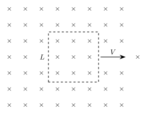
- AP EAPCET 2026Set ap-2026-05-19-FN1 markMCQQ.A conducting square loop of side L moves with a uniform speed V in a region of uniform magnetic field acting perpendicular to the plane of the loop and directed into it as shown in figure. The emf induced in the loop is [FIGURE] (a square conducting loop of side L moves with velocity V to the right, fully inside a region of uniform magnetic field B directed into the page, shown by rows of x symbols) (A) BLV (B) 2BLV (C) zero (D) 2BLV
›Reveal solutionSolution
The key idea is that motional emf requires a change in magnetic flux through the loop. Since the entire loop moves within a uniform field, the flux remains constant, so the induced emf is zero. The correct option is (C).
Concept and Intuition: Motional Emf
When a conductor moves through a magnetic field, charges inside experience a magnetic force q(v×B), which can drive a current if there is a complete circuit. This is the origin of motional emf. However, the emf induced in a closed loop is given by Faraday’s law:
E=−dtdΦB
where ΦB is the magnetic flux through the loop. The crucial point: only a change in flux produces an emf. If the loop moves entirely inside a uniform field, the number of field lines passing through it stays the same — no change, no emf. Many students mistakenly think that motion alone guarantees an emf, but that’s only true if the loop is entering or leaving the field, or if the field itself varies.
Let’s work through the reasoning step by step.
-
Define the situation
The loop is a square of side L, moving with constant velocity V to the right. The magnetic field B is uniform, directed into the page (shown by ‘x’ symbols), and extends over the entire region shown — there is no boundary where the field ends within the diagram. The loop is completely inside this uniform field at all times.
-
Calculate the magnetic flux through the loop
Magnetic flux is given by
ΦB=∫B⋅dA
Since B is uniform and perpendicular to the plane of the loop (into the page), and the loop’s area is L2, the flux simplifies to
ΦB=B⋅(area)=BL2
The direction (sign) is constant, so we can treat it as a positive number.
- Does the flux change as the loop moves? The loop moves to the right, but the field is uniform everywhere. The area L2 does not change, and B does not change. Therefore,
dtdΦB=0
No matter how fast or how far the loop moves, as long as it stays entirely within the uniform field, the flux remains constant.
- Apply Faraday’s law
E=−dtdΦB=0
Hence, the induced emf in the loop is zero.
-
Address a common misconception
Watch outA student might think: “But each side of the loop is moving through the field, so each side should have a motional emf BLV!” This is true for an open conductor, but in a closed loop, the emfs on opposite sides cancel. For example, the right side moving to the right has an upward induced emf (by the right-hand rule), while the left side moving to the right has a downward induced emf — they are equal and opposite, so the net emf around the loop is zero. The flux argument is simpler and more general.
-
Confirm with the given options
The choices are:
(A) BLV
(B) 2BLV
(C) zero
(D) 2BLV
Only option (C) matches our result.
TipA neat shortcut: If a closed loop moves entirely within a uniform magnetic field, the flux is constant → emf = 0. This holds for any shape or orientation, as long as the field is uniform and the loop doesn’t rotate.
✓Final answerThe correct option is (C).
ANSWER: C
-
- AP EAPCET 2025Set eng-2025-05-21-AN1 markMCQQ.A horizontal telegraph wire of length 30 m spread east to west fell down freely from a height of 20 m. If the resistance of the wire is 40 Ω and the horizontal component of the earth's magnetic field at the place is 2×10⁻⁵ T, then the induced current when the wire reaches the ground is (Acceleration due to gravity =10 ms−2) (A) 0.3 mA (B) 3 mA (C) 3 A (D) 0.03 A
›Reveal solutionSolution
Motional EMF is induced in the falling east-west wire by the earth's horizontal magnetic field component; combined with Ohm's law this gives a current of 0.3 mA.
Concept and Intuition
As the horizontal wire (oriented east-west) falls freely, it moves vertically through the earth's horizontal magnetic field component BH, which is perpendicular to both the wire's length and its velocity. This generates a motional EMF ε=BHLv, where v is the wire's instantaneous speed. This EMF drives a current through the wire's own resistance (treating it as a simple closed-loop equivalent circuit as is conventional for this classic problem).
Step-by-Step Solution
- Find the speed at the ground using free fall: v=2gh=2×10×20=400=20 m/s.
- Compute EMF: ε=BHLv=(2×10⁻⁵)(30)(20)=2×10−5×600=1.2×10⁻² V.
- Apply Ohm's law: I=ε/R=401.2×10−2=3×10−4 A.
- Convert: 3×10⁻⁴ A=0.3 mA.
Common Mistakes
- Forgetting to convert to v via kinematics and instead using h directly in the EMF formula.
- Mis-converting amps to milliamps (off by factor of 10 or 1000).
✓Final answerThe correct option is (A) — 0.3 mA.
ANSWER: A
- AP EAPCET 2025Set eng-2025-05-22-AN1 markMCQQ.A metallic disc of radius 0.3 m is rotating with a constant angular speed of 60 rads−1 in a plane perpendicular to a uniform magnetic field of 5×10⁻² T. The emf induced between a point on the rim and centre of the disc is (A) 0.06 V (B) 0.612 V (C) 1.35 V (D) 0.135 V
›Reveal solutionSolution
This tests the motional-emf formula for a rotating conducting disc in a magnetic field. Using ε=21BωR2 gives ε=0.135 V.
Concept and Intuition
Every radial element of the spinning disc is itself a tiny "rod" moving through the magnetic field with a speed that increases linearly from zero at the centre to ωR at the rim. Each element contributes a motional emf dε=Bvdr=B(ωr)dr, and integrating these contributions from the centre to the rim gives the total emf between those two points — analogous to a rotating conducting rod (the Faraday disc / homopolar generator).
Step-by-Step Solution
- Consider a thin element at radius r, thickness dr, moving with speed v=ωr.
- Motional emf of this element: dε=Bvdr=Bωrdr.
- Integrate from r=0 to r=R:
ε=∫0RBωrdr=21BωR2
- Substitute B=5×10⁻² T, ω=60 rads−1, R=0.3 m:
ε=21(5×10⁻²)(60)(0.3)2=21(0.05)(60)(0.09)
=21(0.27)=0.135 V
Common Mistakes
- Forgetting the factor of 21 that comes from integrating r over the disc (using ε=BωR2 instead).
- Using diameter instead of radius for R.
✓Final answerThe correct option is (D) — 0.135 V.
ANSWER: D
- AP EAPCET 2025Set eng-2025-05-23-FN1 markMCQQ.If a wheel with 24 metallic spokes each 40 cm long is rotated with a speed of 180 rev/min in a plane normal to the horizontal component of earth's magnetic field, the emf induced between the axle and the rim of the wheel is E. If the number of spokes is made 12 and the wheel is rotated with a speed of 90 rev/min in the same field, the induced emf is (A) E (B) 2E (C) 4E (D) 0.5E
›Reveal solutionSolution
All spokes of the wheel are in parallel between the same two terminals (axle and rim), so the induced emf depends only on B, ω, and spoke length L — not on the number of spokes. Halving ω (spoke length unchanged) halves the emf.
Concept and Intuition
Each metallic spoke is a conducting rod rotating about one end (the axle) in a magnetic field perpendicular to the plane of rotation. A rotating rod of length L with angular velocity ω generates an emf ε=21BωL2 between its two ends, exactly like a rod sweeping out area. Since every spoke reaches from the same axle to the same rim, all the spokes are connected between the same pair of nodes — they are in parallel, not in series. A parallel combination of identical emf sources (each with the same emf and internal resistance) still delivers that same single-spoke emf between the two terminals; adding more spokes in parallel does not add up the emfs.
Step-by-Step Solution
- EMF of a single rotating spoke: ε=21BωL2.
- Since all spokes connect the same axle to the same rim, they act as parallel identical sources; the net emf between axle and rim equals that of one spoke: E=21Bω1L2, independent of the spoke count (24 originally).
- In the new situation, the number of spokes changes to 12 — irrelevant to the emf, since spokes are in parallel regardless of count.
- Spoke length L is unchanged (still 40 cm) and the magnetic field is unchanged.
- Angular speed changes from ω1 (180 rev/min) to ω2 (90 rev/min) = ω1/2.
- New emf: E′=21Bω2L2=21B(2ω1)L2=21E.
Common Mistakes
- Assuming the emf scales with the number of spokes (treating them as in series), which would wrongly give E′=2412⋅18090E or similar — spokes sharing both terminals are in parallel, and parallel identical sources don't add.
- Forgetting that the number of spokes is a distractor entirely irrelevant to the answer.
✓Final answerThe correct option is (D) — 0.5E.
ANSWER: D
- AP EAPCET 2024Set ap-2024-05-17-FN1 markMCQQ.A helicopter has metallic blades with length 4 m extending outward from the central point and rotating at 3 revs−1. If the vertical component of earth's magnetic field is 40 μT, then the emf induced between the blade tip and the central point is (A) 3.14 mV (B) 2.83 mV (C) 16 mV (D) 6 mV
›Reveal solutionSolution
A rotating rod in a perpendicular magnetic field generates an EMF ε=21BωL2 between its centre and tip; substituting the given values gives about 6 mV. Answer: (D) 6 mV.
Concept and Intuition
Each helicopter blade is a straight conductor rotating about one end (the hub) in the (locally uniform) vertical component of Earth's magnetic field. Every small element of the rotating rod experiences a motional EMF dε=Bvdr=B(ωr)dr, and integrating from the hub (r=0) to the tip (r=L) gives the classic result ε=21BωL2 — the same formula used for a conducting rod/disc rotating in a magnetic field (e.g. the Faraday disc).
Step-by-Step Solution
- Angular speed: ω=2πf=2π(3)=6π≈18.85 rad/s.
- Blade length L=4 m, field B=40 μT=40×10−6 T.
- EMF for a rod rotating about one end: ε=21BωL2.
- Substitute: ε=21(40×10−6)(18.85)(16).
- Compute: 40×10−6×18.85=7.54×10⁻⁴; times 16=1.206×10⁻²; times 21=6.03×10⁻³ V =6.03 mV ≈6 mV.
Common Mistakes
- Using L instead of L2 (or forgetting the factor of 21 that comes from integrating over the rod's length).
- Using frequency f directly in the formula instead of converting to angular frequency ω=2πf.
✓Final answerThe correct option is (D) — 6 mV.
ANSWER: D
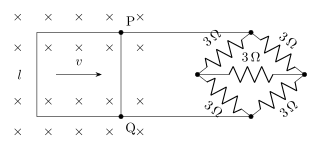
- AP EAPCET 2024Set eng-2024-05-22-AN1 markMCQQ.A metallic wire loop of side (l) 0.1 m and resistance of 1Ω is moved with a constant velocity in a uniform magnetic field of 2 Wm−2 as shown in the figure. The magnetic field is perpendicular to the plane of the loop. The loop is connected to a network of resistors. The velocity of loop so as to have a steady current of 1 mA in loop is [FIGURE] (a square wire loop of side l is shown moving with velocity v to the right through a region of magnetic field directed into the page (marked with x symbols); the loop's two terminals P (top) and Q (bottom) connect via wires to a network of five 3Ω resistors arranged in a diamond/bridge pattern -- two 3Ω resistors forming the upper branches, two 3Ω resistors forming the lower branches, and one 3Ω resistor as the central bridging element) (A) 0.67 cms−1 (B) 2 cms−1 (C) 3 cms−1 (D) 4 cms−1
›Reveal solutionSolution
The motional emf of a sliding loop drives current through a balanced Wheatstone-bridge network of five equal resistors; recognizing the balance simplifies the network to 3Ω, and setting the resulting current to 1 mA gives the required velocity.
Concept and Intuition
A conducting loop moving with velocity v through a uniform field B perpendicular to its plane acts as a source of motional emf ε=Bvl (only the leading/trailing side cutting field lines matters for a simple translating loop of width l). This emf drives current through the loop's own resistance in series with whatever external network is connected across its terminals P and Q. Here that external network is a Wheatstone bridge of five identical 3Ω resistors — since all four arms are equal (3:3::3:3), the bridge is balanced, meaning the two "middle" nodes sit at the same potential and the fifth (bridging) resistor carries no current at all. It can therefore be deleted without changing the network's behaviour.
Step-by-Step Solution
- Balanced-bridge simplification: with the bridge resistor removed, the network becomes two series pairs of 3Ω+3Ω=6Ω each, connected in parallel between P and Q: Rext=6∥6=3Ω.
- Total resistance in the circuit (loop's own resistance in series with the external network, as the loop is the emf source): Rtotal=Rloop+Rext=1+3=4Ω.
- Motional emf: ε=Bvl=2×v×0.1=0.2v.
- Current: I=Rtotalε=40.2v=0.05v.
- Set I=1 mA=1×10⁻³ A: 0.05v=10−3⇒v=0.02 m/s=2 cm/s.
Common Mistakes
- Trying to reduce the bridge network by naive series-parallel combination without first checking for balance (which would give the wrong, more complicated, equivalent resistance).
- Forgetting to add the loop's own 1Ω resistance to the external 3Ω before computing the current.
✓Final answerThe correct option is (B) — 2 cms−1.
ANSWER: B
- AP EAPCET 2023Set eng-2023-05-15-FN1 markMCQQ.In an ac generator, if coil of N turns and area A is rotated at υ revolutions per second in a uniform magnetic field B, then the motional emf produced is equal to (At t=0 s, the coil is perpendicular to the field) (A) NBA(2πυ)sin(2πυt) (B) NBA2(2πυ)sin(2πυt) (C) N2B2A2(2πυ)sin(2πυt) (D) NBA(4πυ)sin(2πυt)
›Reveal solutionSolution
Faraday's law applied to a rotating coil gives the standard AC-generator EMF e=NBAωsin(ωt) with ω=2πυ, matching option (A).
Concept and Intuition
An AC generator works by rotating a coil in a uniform magnetic field, continuously changing the flux linkage through it and thereby inducing an EMF (Faraday's law of electromagnetic induction). If the coil starts perpendicular to B at t=0 (flux maximum at t=0), the flux varies as a cosine and the EMF — being −dΦ/dt — comes out as a sine function, peaking a quarter-cycle later.
Step-by-Step Solution
- Flux through the coil at angle θ=ωt from the perpendicular position: Φ(t)=NBAcos(ωt), where ω=2πυ (υ = revolutions per second).
- Induced EMF: e=−dtdΦ=−NBA×(−ωsinωt)=NBAωsin(ωt).
- Substitute ω=2πυ: e=NBA(2πυ)sin(2πυt).
- This matches the form of option (A) exactly, with correct powers of N, B, A (all to the first power) and the correct angular frequency factor.
Common Mistakes
- Squaring N, B, or A (as in some distractor options) — the EMF is linear in each of these quantities, not quadratic.
- Using 4πυ instead of 2πυ for the angular frequency — a common factor-of-two slip.
✓Final answerThe correct option is (A) — NBA(2πυ)sin(2πυt).
ANSWER: A
- AP EAPCET 2023Set eng-2023-05-16-AN1 markMCQQ.An ac generator converts (A) electrical energy into mechanical energy. (B) electrical energy into magnetic energy. (C) mechanical energy into magnetic energy. (D) mechanical energy into electrical energy.
›Reveal solutionSolution
An AC generator uses electromagnetic induction to turn mechanical rotation into electrical energy.
Concept and Intuition
A generator works on Faraday's law of electromagnetic induction: mechanically rotating a coil within a magnetic field (or a magnet within a coil) changes the magnetic flux through the coil, inducing an EMF. This is the exact reverse of a motor, which converts electrical energy into mechanical energy.
Step-by-Step Solution
- In an AC generator, an external mechanical agent (e.g. a turbine, hand-crank, or engine) does work to rotate the coil/armature.
- As the coil rotates in the magnetic field, the flux linkage changes with time, inducing an EMF (Faraday's law).
- This induced EMF drives a current in the external circuit — meaning mechanical energy input has been converted into electrical energy output.
- This is the opposite conversion of what a motor does (electrical → mechanical).
Common Mistakes
- Confusing a generator with a motor (which does the reverse conversion, electrical to mechanical).
✓Final answerThe correct option is (D) — mechanical energy into electrical energy.
ANSWER: D
- AP EAPCET 2022Set ap-2022-07-12-AN1 markMCQQ.A wire of length 20 cm is moving with a velocity of 180 m min−1 perpendicular to a magnetic field. If the induced emf in the wire is 3 V, the magnitude of the field in tesla is (A) 2 (B) 3 (C) 5 (D) 10
›Reveal solutionSolution
A straight conductor moving perpendicular to a magnetic field develops a motional emf ε=BLv; solve for B given the other three quantities.
Concept and Intuition
When a conducting rod of length L moves with speed v perpendicular to a magnetic field B, the free charges in the rod experience a magnetic force that separates charge until an equilibrium (motional) emf develops: ε=BLv.
Step-by-Step Solution
- Convert velocity: v=180 m/min=60180=3 m/s.
- Length: L=0.2 m.
- From ε=BLv: B=Lvε=0.2×33=0.63=5 T.
Common Mistakes
- Forgetting to convert the velocity from m/min to m/s before using it.
✓Final answerThe correct option is (C) — 5.
ANSWER: C
- AP EAPCET 2021Set eng-2021-08-19-FN1 markMCQQ.An electric generator is based on _________ (A) Faraday's laws of electromagnetic induction (B) Motion of charged particles in an electromagnetic field (C) Fission of Uranium by slow neutrons (D) Newton's laws of motion
›Reveal solutionSolution
The electric generator is a direct application of Faraday's law: rotating a coil in a magnetic field changes the flux through it, inducing an EMF.
Concept and Intuition
A generator is essentially the reverse of a motor: mechanical rotation of a coil inside a magnetic field (or vice versa) continuously changes the magnetic flux linked with the coil. By Faraday's law, ε=−dtdΦB, this changing flux induces an EMF, which drives current through an external circuit.
Step-by-Step Solution
- Identify the working principle needed: converting mechanical rotation into electrical EMF.
- Faraday's law of electromagnetic induction states that an EMF is induced whenever the magnetic flux through a circuit changes.
- In a generator, the coil's orientation relative to the field constantly changes as it rotates, so ΦB(t)=BAcos(ωt) varies with time, inducing a sinusoidal EMF.
- None of the other listed principles (motion of charged particles in an EM field, nuclear fission, Newton's laws) describe the generator's basic working.
- Hence the generator is based on Faraday's laws of electromagnetic induction.
Common Mistakes
- Confusing the generator (uses Faraday's law) with devices based on the motion of charged particles in fields, like a cyclotron or CRT.
✓Final answerThe correct option is (A) — Faraday's laws of electromagnetic induction.
ANSWER: A
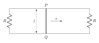
- AP EAPCET 2021Set eng-2021-08-23-AN1 markMCQQ.A rectangular loop circuit has a sliding wire PQ as shown in the figure. The loop is placed in a magnetic field 'B', perpendicular to its plane. The resistance of the wire PQ is R. If the wire moves with constant velocity 'v', then find the current flowing through the wire PQ? [FIGURE] (a rectangular loop with a resistor R forming the left side, another resistor R forming the right side, and a sliding wire PQ (also of resistance R) vertically across the middle at distance l from the left side, moving to the right with velocity v) (A) 3RBlv (B) 2RBlv (C) 2R3Blv (D) 3R2Blv
›Reveal solutionSolution
The moving wire PQ is an EMF source of its own resistance R; the fixed resistors on either side act in parallel as its external load, giving total resistance 3R/2 and hence a current of 3R2Blv through PQ.
Concept and Intuition
As PQ slides with velocity v in field B, motional EMF ε=Blv is generated across it, and PQ itself has resistance R. Since the rails are (implicitly) resistance-free, current from PQ can return via either the left resistor or the right resistor — both connect the same top and bottom rails, so they are electrically in parallel with each other, both acting as the external circuit for the source PQ.
Step-by-Step Solution
- EMF source: PQ, with ε=Blv and internal resistance R.
- External resistance seen by PQ: the left R and right R are both connected across the same two rails (top and bottom), so they are in parallel: Rext=R+RR⋅R=2R.
- Total resistance in the circuit as seen by the source: Rtotal=R+2R=23R.
- Current delivered by the source (this is the current that flows through PQ, since all current must pass through the source itself): I=Rtotalε=3R/2Blv=3R2Blv.
Common Mistakes
- Treating the two outer resistors as being in series instead of parallel (they are in parallel because both connect the same top/bottom rail pair).
- Forgetting that PQ's own resistance R must be added in series with the external parallel combination to get total circuit resistance.
✓Final answerThe correct option is (D) — 3R2Blv.
ANSWER: D
🎓Unlock everything free for 14 days
- ✓Full step-by-step solutions
- ✓Concept-first explanations
- ✓Methods, shortcuts & mistakes
- ✓PYQ mapping + timed mock tests
Full access for 14 days. No credit card required.