Q.Consider a magnet surrounded by a wire with an on/off switch S. If the switch is thrown from the off position (open circuit) to the on position (closed circuit), will a current flow in the circuit? Explain.
🔒You're viewing a preview — the full solution, concept, methods & PYQ mapping are locked.
🔒 Start your 14-day free trial to unlock the full solution →Concept understanding — Electromagnetic Induction
Electromagnetic Induction
Electromagnetic induction is the phenomenon in which a changing magnetic flux through a circuit produces an electromotive force (emf) — and hence a current, if the circuit is closed. It is the single idea behind generators, transformers, inductors, and the entire AC power grid.
The Central Discovery
Michael Faraday found (1831) that a current is induced in a coil not when a magnet sits still near it, but only while the magnet moves — that is, only while the magnetic flux linked with the coil is changing. A steady magnet, however strong, induces nothing.
Magnetic Flux
The key quantity is magnetic flux ΦB through a surface of area A in a field B:
ΦB=B⋅A=BAcosθ
where θ is the angle between B and the area's normal. Its SI unit is the weber (Wb), where 1 Wb=1 T⋅m2.
Flux can change in three distinct ways, and any of them induces an emf:
- the field strength B changes,
- the area A of the loop changes,
- the orientation θ changes (a coil rotating in a field — the basis of the generator).
Faraday's Law
The induced emf equals the negative rate of change of flux. For a coil of N turns:
E=−NdtdΦB
The faster the flux changes, the larger the emf. This is why a magnet dropped quickly through a coil gives a bigger deflection than one moved slowly.
Lenz's Law — the Minus Sign
The negative sign expresses Lenz's law: the induced current flows in the direction that opposes the change producing it. Push a magnet's north pole toward a coil, and the coil's near face becomes a north pole to repel it; pull it away, and the face becomes a south pole to attract it. This is simply energy conservation — you must do work against this opposition, and that work becomes the electrical energy of the induced current.
Motional emf
A special, very useful case: a conducting rod of length l moving with speed v perpendicular to a field B sweeps out area and develops an emf
E=Blv
Here the emf arises because the free charges in the rod experience a magnetic force qv×B, which drives them along the rod. …
Why this formula?
Electromagnetic Induction
Electromagnetic induction is the effect discovered by Faraday: a changing magnetic flux through a circuit drives an induced EMF (and hence a current). The key word is changing — a steady field, however strong, induces nothing.
Magnetic flux
Flux measures how many field lines thread a surface bounded by the loop:
ΦB=∫B⋅dA=BAcosθ
It can change three ways: by changing B, by changing the area A, or by rotating the loop (changing θ).
Faraday's law
The induced EMF equals the rate of change of flux:
E=−dtdΦB
For a coil of N turns, E=−NdtdΦB. The EMF depends on how fast the flux changes, not on the flux itself — a slow change gives a small EMF, a rapid change a large one.
Lenz's law — the minus sign …
The key idea is Electromagnetic Induction: a changing magnetic flux through a circuit induces an EMF, which drives a current if the circuit is closed.
- A stationary magnet produces a constant magnetic field. The wire loop is fixed in place, so the magnetic flux through the loop is constant.
- Throwing the switch from open to closed does not change the magnetic field or the area of the loop. The flux remains constant.
- An induced EMF (and therefore current) requires a change in magnetic flux with time (E=−dΦB/dt). Since dΦB/dt=0, no EMF is induced. …
The key idea is that electromagnetic induction requires a changing magnetic flux through the circuit. Throwing the switch from open to closed does not change the magnetic field from the magnet — so no induced current flows. The final answer is no current flows.
Why This Question Tests a Common Misconception
Many students instinctively think that "closing a switch near a magnet" should produce current — after all, we often associate switches with turning things on. But electromagnetic induction depends on change, not just presence. A steady magnet produces a steady magnetic field. If the circuit is open, no current can flow. When you close the switch, you simply complete the path — but the magnetic flux through the loop hasn't changed at all. Without a change in flux, there is no induced EMF, and therefore no current.
Let's walk through this carefully.
Step-by-Step Reasoning
- Recall Faraday's Law of Induction The induced electromotive force (EMF) in a closed loop is given by:
E=−dtdΦB
where ΦB is the magnetic flux through the loop. The key point: only a time-varying flux produces an EMF.
- Identify the magnetic flux in this setup The magnet produces a steady magnetic field. The wire loop (when closed) has a certain area and orientation relative to the magnet. The flux through the loop is:
ΦB=∫B⋅dA
Since the magnet is stationary and the loop is fixed, B at every point on the loop is constant in time.
- What happens when the switch is thrown? Before the switch is closed, the circuit is open — no current can flow even if an EMF existed. When you close the switch, you simply connect the wire ends. The loop's area, shape, and position relative to the magnet do not change. The magnetic field from the magnet remains unchanged. Therefore:
dtdΦB=0
at all times, including the instant the switch is thrown.
- Consequence: No induced EMF, no current …
Method: The "Is Anything Actually Changing?" Test for Static-Setup Induction Questions
A whole class of EMI conceptual questions describes an action (closing a switch, connecting a wire, completing a circuit) that sounds like it should "activate" something — but the real physics test is whether that action changes the magnetic flux, not whether it changes the circuit's connectivity.
Steps
Step 1: List everything present in the setup that could produce or carry flux
Identify the magnetic field source (a magnet, a current-carrying coil) and the loop/circuit that could have flux linked through it.
Step 2: Ask specifically: does the described action change B, the loop's area, or its orientation?
Faraday's law only cares about
dtdΦB,ΦB=∫B⋅dA
Closing a switch changes the circuit's connectivity (whether current can flow), but by itself does not move the magnet, does not reshape the loop, and does not reorient anything. If none of B, A, or θ actually changes, then ΦB was already constant before the switch closed and remains exactly as constant afterward.
Step 3: Distinguish "circuit is now complete" from "flux is now changing"
These are two independent facts and it's easy to conflate them. A closed circuit only allows current to flow if there is an emf to drive it. Completing the path itself generates no emf — the emf still requires dΦB/dt=0, which this action doesn't provide. …
Showing the 12 most recent of 45 on this concept.
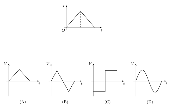
- AP EAPCET 2026Set eng-2026-05-12-FN1 markMCQQ.The current I in an induction coil is varying with time t as shown in the figure: [FIGURE: I–t graph — a symmetric triangular pulse; the current I rises linearly from 0 to a peak value and then decreases linearly back to 0]. Which one of the following graphs shows the variation of voltage in the coil with time t? (A) [FIGURE: V–t graph — a single symmetric triangular pulse lying entirely above the axis: V rises linearly from 0 to a peak value, then falls linearly back to 0 (the same triangular shape as the given I–t graph)] (B) [FIGURE: V–t graph — V rises linearly from 0 to a positive peak, falls linearly through zero to a negative peak of equal magnitude, then rises back to 0 (a positive triangular lobe immediately followed by a negative triangular lobe, i.e. a zig-zag waveform)] (C) [FIGURE: V–t graph — a rectangular (square) wave: V is constant and negative for the first half of the time interval, then jumps abruptly to a constant positive value of equal magnitude for the second half] (D) [FIGURE: V–t graph — one smooth rounded lobe: V rises from 0, curves up to a rounded positive peak, curves back down through zero, dips to a rounded negative trough of equal magnitude, then returns to zero (resembling one full cycle of a sine wave)]
›Reveal solutionSolution
This tests the relation V=−LdI/dt for a piecewise-linear current; a triangular I-t graph gives a rectangular (square-wave) V-t graph.
Concept and Intuition
Induced EMF depends only on the rate of change of current, not on the current's value itself. A triangular current pulse has a constant (but different-signed) slope during its rising and falling halves — the slope itself doesn't vary smoothly, it switches abruptly from one constant value to another (with a sign flip) right at the peak. Since voltage tracks the slope, not the current, the voltage must also be piecewise-constant: it jumps sharply at the current's peak, producing a rectangular wave rather than mirroring the current's triangular shape.
Step-by-Step Solution
- Write the induced voltage as V=−LdtdI.
- During the rising half of the triangular pulse, I increases linearly, so dtdI is a positive constant; hence V is a constant negative value.
- During the falling half, I decreases linearly, so dtdI is a negative constant of the same magnitude (symmetric triangle); hence V is a constant positive value of equal magnitude.
- At the exact peak, the slope switches abruptly, so V jumps discontinuously from the negative constant to the positive constant. …
- AP EAPCET 2026Set eng-2026-05-14-FN1 markMCQQ.In a coil the current varies from −3A to +3A in 4s, and induces an emf 0.2V. The self-inductance of the coil is (A) 0.133 H (B) 0.266 H (C) 0.65 H (D) 0.532 H
›Reveal solutionSolution
This tests the self-inductance relation ε=LdI/dt with a signed current change. Answer: 0.133 H.
Concept and Intuition
Self-induced emf is proportional to the rate of change of current through the coil, not the current's absolute value. Going from −3 A to +3 A is a total swing of 6 A (not 0 A — the current doesn't stay the same, it reverses and changes by the full 6 A), and dividing by the time taken gives the average dI/dt, which plugs directly into ε=LdI/dt.
Step-by-Step Solution
- Change in current: ΔI=If−Ii=3−(−3)=6 A.
- Time taken: Δt=4 s.
- Rate of change: dtdI=46=1.5 A/s. …
- AP EAPCET 2026Set eng-2026-05-13-AN1 markMCQQ.In a coil of resistance 10Ω, the induced current developed by changing magnetic flux through it is shown in figure as a function of time. The magnitude of charge in flux through the coil in weber is (the graph shows current i, in amp, decreasing linearly with time t, in s, from i=4 A at t=0 to i=0 at t=0.1 s) (A) 8 (B) 6 (C) 4 (D) 2
›Reveal solutionSolution
The charge that flows through a coil during a flux change is q=Δϕ/R, so Δϕ=qR. The charge is the area under the current–time graph. Answer: 2 Wb.
Concept and Intuition
Faraday's law gives the induced EMF as ε=−dϕ/dt, and with ε=iR, we get i=−R1dtdϕ. Integrating over time, the total charge that flows is q=∫idt=RΔϕ (in magnitude) — so the charge equals the area under the i–t graph, independent of exactly how i varies with time.
Step-by-Step Solution
- The i–t graph is a straight line from i=4A at t=0 to i=0 at t=0.1s — a right triangle. …
- AP EAPCET 2026Set eng-2026-05-15-AN1 markMCQQ.A current carrying loop is placed perpendicular to the direction of a uniform magnetic field of 40 mT. If the radius of the loop decreases at constant rate of 1.4 mms−1, the induced emf when the radius of the loop becomes 2.5 cm is (A) 6.6 μV (B) 2.2 μV (C) 4.4 μV (D) 8.8 μV
›Reveal solutionSolution
A shrinking loop in a uniform field induces an emf from the changing enclosed area; the answer is 8.8 μV.
Concept and Intuition
The flux through the loop is Φ=Bπr2 (loop perpendicular to B). As the radius shrinks, the enclosed area — and hence the flux — changes with time, inducing an emf ε=−dtdΦ=−B⋅2πrdtdr (using the chain rule on r2).
Step-by-Step Solution
- ∣ε∣=B⋅2πr⋅dtdr.
- Substitute B=40×10−3 T, r=2.5×10⁻² m, dtdr=1.4×10⁻³ m/s.
- 2πr=2π(0.025)=0.15708 m. …
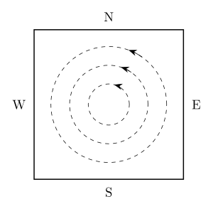
- AP EAPCET 2026Set eng-2026-05-15-FN1 markMCQQ.A metal sheet is placed in a magnetic field whose magnitude changes from zero to maximum. The direction of eddy currents produced in the plate is shown in the figure. Then the direction of magnetic field is [FIGURE: a square metal plate with N marked at top, S at bottom, W at left, E at right; concentric circular eddy-current loops are shown inside the plate with arrows indicating a counter-clockwise sense] (A) Normally inwards (B) Normally outwards (C) From West to East (D) From North to South
›Reveal solutionSolution
Reading the eddy-current sense with the right-hand rule and applying Lenz's law (opposing the increasing flux) shows the external field points into the page. Answer: (A).
Concept and Intuition
Eddy currents are induced only by a flux change normal to the sheet — a field lying in the plane of the sheet (W-to-E or N-to-S) cannot drive circular loops confined to that plane. So the answer must be one of the two 'normal' options. Lenz's law says the induced current always opposes the change in flux that caused it; since the field is increasing from zero to a maximum, the induced current's own field must point opposite to the external field, partially cancelling the increase.
Step-by-Step Solution
- The loops are confined to the plane of the sheet, so the driving flux must be along the sheet's normal (into or out of the page) — this rules out the W→E and N→S options.
- Trace the eddy-current sense as described: current rises along the E (right) side toward N, crosses the top moving toward W, and falls along the W (left) side toward S — tracing this out is a counter-clockwise sense as seen by someone looking at the page.
- Apply the right-hand rule to this counter-clockwise loop: curl the right-hand fingers along the current's direction (counter-clockwise); the thumb points out of the page, toward the viewer. So the eddy current's own magnetic field points out of the page at the centre. …
- AP EAPCET 2026Set ap-2026-05-19-AN1 markMCQQ.A conducting circular loop with area 3.5×10⁻³ m2 and resistance 10Ω is placed normally in a magnetic field B(t)=0.4sin(50πt) tesla. The net charge flowing through the loop during t=0 to t=10 ms is (Assume the field is uniform over the loop) (A) 0.14 mC (B) 21 mC (C) 6 mC (D) 7 mC
›Reveal solutionSolution
Charge through a loop from changing flux is q=ΔΦ/R, independent of how B varied in between — only the endpoint values of B matter.
Concept and Intuition
The induced charge q=∫Idt=∫R1dtdΦdt=RΔΦ depends only on the net change in flux between the initial and final instants, not on the details of the time-variation in between (as long as we integrate over the correct interval). This makes the calculation depend only on B(0) and B(10ms).
Step-by-Step Solution
- B(t)=0.4sin(50πt).
- At t=0: B(0)=0.4sin(0)=0.
- At t=10ms=0.01s: argument =50π×0.01=0.5π=π/2, so B(0.01)=0.4sin(π/2)=0.4T.
- ΔB=0.4−0=0.4T; ΔΦ=AΔB=3.5×10−3×0.4=1.4×10⁻³Wb. …
- AP EAPCET 2026Set eng-2026-05-18-AN1 markMCQQ.A circular coil of radius 8 cm, 400 turns and resistance 2Ω is placed with its plane perpendicular to the horizontal component of the earth's magnetic field. It is rotated about its vertical diameter through 180° in 0.30 sec. Horizontal component of the earth's magnetic field at the place is 3×10⁻⁵ T. The magnitude of current induced in the coil is approximately (A) 4×10⁻² A (B) 8×10⁻⁴ A (C) 8×10⁻² A (D) 1.92×10⁻³ A
›Reveal solutionSolution
This tests average EMF/current from a flux reversal (coil flipped 180° in a uniform field) — answer is 8×10⁻⁴ A.
Concept and Intuition
When a coil's plane is perpendicular to a magnetic field, the field lines pass straight through it, so the flux linkage is maximum: Φ=NBA. Flipping the coil by 180° about a diameter doesn't change the magnitude of flux through it, but the normal now points the opposite way, so the flux becomes −NBA. The coil has therefore swept through a flux change of 2NBA, not zero — this is the classic trick in this problem type. Since we're only given a total rotation time (not the instantaneous ωt dependence), we use the average-EMF form of Faraday's law over that interval.
Step-by-Step Solution
- Area of coil: A=πr2=π(0.08)2=3.14159×0.0064=0.02011 m2.
- Initial flux (normal ∥BH): Φi=NBHA.
- After 180° rotation, normal reverses: Φf=−NBHA.
- Magnitude of flux change: ∣ΔΦ∣=∣Φf−Φi∣=2NBHA=2×400×(3×10−5)×0.02011. =2×400×3×10−5×0.02011=4.826×10⁻⁴ Wb.
- Average induced EMF: ε=Δt∣ΔΦ∣=0.304.826×10−4=1.609×10⁻³ V. …
- AP EAPCET 2025Set eng-2025-05-22-FN1 markMCQQ.A coil of 45 turns and radius 4 cm is placed in a uniform magnetic field such that its plane is perpendicular to the direction of the field. If the magnetic field increases from 0 to 0.70 T at a constant rate in a time interval of 220 s, then the induced emf in the coil is (A) 0.32 mV (B) 0.50 mV (C) 0.72 mV (D) 0.96 mV
›Reveal solutionSolution
Faraday's law for a multi-turn coil in a linearly changing field gives ε=NAdB/dt; substituting the given numbers yields 0.72 mV.
Concept and Intuition
Faraday's law states that an EMF is induced in a coil whenever the magnetic flux linked with it changes: ε=−NdtdΦ. Since the coil's plane is perpendicular to B, the flux through one turn is simply Φ=BA (no angle factor needed), and because the field changes at a constant rate, dtdB is just ΔB/Δt. Multiplying by the number of turns N accounts for the fact that each turn contributes its own EMF, and these add in series.
Step-by-Step Solution
- Area of the coil: A=πr2=π(0.04 m)2=π×1.6×10⁻³≈5.027×10⁻³ m2.
- Rate of change of field: dtdB=220 s0.70 T−0=3.1818×10⁻³ T/s. …
- AP EAPCET 2025Set ap-2025-05-19-AN1 markMCQQ.When the current in a coil decreases from 10 A to I in a time of 2 seconds, the induced emf in the coil is e1. When the current in the coil decreases from I to zero in 4 seconds, the induced emf in the coil is e2. If the ratio of the induced emfs e1:e2 is 2 : 3, then the value of I is (A) 3.75 A (B) 7.5 A (C) 5 A (D) 2.5 A
›Reveal solutionSolution
Using e=LΔI/Δt for both intervals and the given ratio e1:e2=2:3 gives I=7.5 A.
Concept and Intuition
The emf induced in a coil due to a changing current is e=−LdtdI, and for a uniform rate of change over an interval Δt, the magnitude is e=LΔt∣ΔI∣. Since the same coil (same self-inductance L) is used in both cases, L cancels out when we take the ratio of the two emfs, leaving an equation purely in terms of I.
Step-by-Step Solution
- First interval: current falls from 10A to I in 2s:
e1=L210−I
- Second interval: current falls from I to 0 in 4s:
e2=L4I
- Given e2e1=32:
LI/4L(10−I)/2=32
- Simplify the left side:
I/4(10−I)/2=2I4(10−I)=I2(10−I)
- So: …
- AP EAPCET 2025Set ap-2025-05-19-FN1 markMCQQ.The device constructed based on the laws of electromagnetic induction is (A) galvanometer (B) electric motor (C) ohm meter (D) electric generator
›Reveal solutionSolution
Among the listed devices, the electric generator is the one whose operating principle is Faraday's law of electromagnetic induction — a changing magnetic flux through a rotating coil induces an emf.
Concept and Intuition
Electromagnetic induction states that a changing magnetic flux through a circuit induces an emf in it. An electric generator exploits this directly: a coil is mechanically rotated within a magnetic field, continuously changing the flux linked with it, which induces an alternating emf — converting mechanical energy into electrical energy.
Step-by-Step Solution
- Galvanometer: works on the torque on a current-carrying coil in a magnetic field (motor effect), not induction.
- Electric motor: converts electrical energy to mechanical energy via the force on a current-carrying conductor in a field — also the motor effect, not induction. …
- AP EAPCET 2025Set ap-2025-05-20-FN1 markMCQQ.The current in a coil decreases from 5 A to zero in a time of 0.1 s. If an average emf of 200 V is induced, then the self inductance of the coil is (A) 20 H (B) 4 H (C) 2 H (D) 40 H
›Reveal solutionSolution
Self-inductance is found from ε=LdI/dt; with the given rate of current change and induced emf, L=4 H.
Concept and Intuition
Self-induction opposes any change in current through a coil, producing an induced emf proportional to the rate of change of current: ε=−LdtdI. The magnitude of this relationship lets us solve for L given the emf and the current's rate of change.
Step-by-Step Solution
- Rate of change of current: dtdI=0.1∣0−5∣=0.15=50 A/s.
- Magnitude of induced emf: ε=LdtdI, so 200=L(50). …
- AP EAPCET 2025Set eng-2025-05-24-FN1 markMCQQ.A coil of resistance 200 Ω is placed in a magnetic field. If the magnetic flux ϕ (in weber) linked with the coil varies with time 't' (in second) as per the equation ϕ=50t2+4, then the current induced in the coil at a time t=2 s is (A) 2 A (B) 1 A (C) 0.5 A (D) 0.1 A
›Reveal solutionSolution
Faraday's law gives the induced EMF as the time-derivative of flux; dividing by the coil resistance gives an induced current of 1 A at t=2 s.
Concept and Intuition
Faraday's law of electromagnetic induction states that the EMF induced in a coil equals the (negative of the) rate of change of magnetic flux linked with it: ε=−dtdϕ. Once you know the EMF, Ohm's law across the coil's own resistance gives the induced current directly (there's no other source in this circuit).
Step-by-Step Solution
- Given ϕ(t)=50t2+4 (in Wb).
- Differentiate: dtdϕ=100t.
- At t=2 s: dtdϕ=100×2=200 V (this is the induced EMF). …
🎓Unlock everything free for 14 days
- ✓Full step-by-step solutions
- ✓Concept-first explanations
- ✓Methods, shortcuts & mistakes
- ✓PYQ mapping + timed mock tests
Full access for 14 days. No credit card required.