Q.Point A is held at −10V and point B is earthed (at 0V). Starting from A, a resistor R is in series with an ideal diode D1 whose arrow (anode to cathode) points from the A/resistor side towards a junction. From that junction the line runs down through a second ideal diode D2 to B; D2's arrow points upward, from the earthed B side towards the junction (its anode is on the B side, its cathode towards the junction). Assuming the diodes to be ideal, which statement is correct?
Concept understanding — P N Junction Biasing
P-N Junction Biasing: The First Meeting
Imagine you have two rooms separated by a door. One room is full of people who want to leave (electrons in the N-side), and the other room is full of empty chairs (holes in the P-side). The door is initially locked — that's the depletion region, a zone with no free charges. Now, what happens if you push on the door from one side, or pull it from the other? That's exactly what biasing does to a P-N junction.
The Unbiased Junction (The Starting Point)
When you bring P-type and N-type semiconductors together, something interesting happens at the boundary. Electrons from the N-side (which has extra electrons) rush toward the P-side (which has extra holes). Holes from the P-side rush toward the N-side. They meet and recombine — an electron falls into a hole, and both disappear as free charges.
This leaves behind a region near the junction with no free charges — just fixed positive ions on the N-side (where electrons left) and fixed negative ions on the P-side (where holes left). This is the depletion region. It acts like a tiny battery: the N-side is positive relative to the P-side, creating a built-in electric field that stops further diffusion. The voltage across this region is about 0.7 V for silicon, 0.3 V for germanium.
The depletion region is not a physical gap — it's a region depleted of mobile charge carriers. The crystal is still continuous.
Forward Bias: Pushing the Door Open
Connect the positive terminal of a battery to the P-side and the negative terminal to the N-side. This is forward bias.
What happens? The external battery's positive terminal repels holes in the P-side toward the junction. The negative terminal repels electrons in the N-side toward the junction. Both carriers are pushed toward each other — they overcome the built-in electric field. The depletion region shrinks.
When the applied voltage exceeds about 0.7 V (for silicon), the depletion region becomes so thin that carriers can cross freely. A large current flows. The junction is now "on" — like a switch closed.
Never apply forward bias without a current-limiting resistor. The junction has very low resistance once forward-biased, and the current can destroy it instantly.
Reverse Bias: Pulling the Door Shut
Now reverse the battery: positive to N-side, negative to P-side. This is reverse bias.
The positive terminal attracts electrons from the N-side away from the junction. The negative terminal attracts holes from the P-side away from the junction. Both carriers are pulled apart. The depletion region widens.
The built-in electric field is now reinforced by the external field. Only a tiny current flows — the reverse saturation current, caused by thermally generated electron-hole pairs in the depletion region. This current is typically in the nanoampere range and is almost independent of the applied voltage (until breakdown).
The junction is "off" — like a switch open.
In reverse bias, the depletion region acts as an insulator. The junction blocks current flow except for a negligible leakage current.
The Precise Statement
I=IS(enkTqV−1)
This is the Shockley diode equation. Here:
- I = diode current
- IS = reverse saturation current (very small, typically 10−12 to 10−15 A for silicon)
- q = electron charge (1.6×10⁻¹⁹ C)
- V = applied voltage (positive for forward bias, negative for reverse bias)
- n = ideality factor (1 for ideal, 1–2 for real diodes)
- k = Boltzmann constant (1.38×10⁻²³ J/K)
- T = absolute temperature (K)
For forward bias (V>0), the exponential term dominates — current grows rapidly. For reverse bias (V<0), the exponential term becomes negligible, and I≈−IS — a tiny constant current.
Summary Table
| Condition | Bias | Depletion Region | Current |
|---|---|---|---|
| No external voltage | Unbiased | Moderate width | Zero net current |
| P positive, N negative | Forward bias | Shrinks | Large (exponential) |
| P negative, N positive | Reverse bias | Widens | Tiny (saturation) |
Why This Matters
Every diode, LED, solar cell, and transistor relies on this principle. A solar cell is just a P-N junction under forward bias from light. A transistor uses two junctions back-to-back. The ability to control current flow with a voltage — to switch between "on" and "off" — is the foundation of all modern electronics.
Remember the mnemonic: Positive to P-side = Forward bias (current flows). Negative to P-side = Reverse bias (current blocked). The arrow in the diode symbol points from P to N — the direction of conventional current when forward-biased.
Forward and reverse biasing of the p-n junction, along with the Shockley diode equation, is a core numerical and conceptual topic in the NCERT Class 12 Physics Semiconductor Electronics chapter, frequently searched as "p-n junction biasing important questions" by CBSE board and JEE Main aspirants. This concept is also essential groundwork for understanding rectifiers and transistor circuits covered later in the same syllabus.
Why this formula?
Why a PN Junction Biases the Way It Does
A PN junction is not a resistor. Its current-voltage behaviour is fundamentally asymmetric — and that asymmetry comes directly from the physics of the depletion region and the energy barrier it creates.
The Unbiased Junction: A Built-in Barrier
When P-type and N-type semiconductors are joined, holes from the P-side diffuse into the N-side, and electrons from the N-side diffuse into the P-side. This diffusion leaves behind fixed, charged ions: negative acceptor ions on the P-side, positive donor ions on the N-side. These ions create an electric field that opposes further diffusion.
The result is a depletion region — a zone with no free carriers — and a built-in potential V0 across it. This potential acts as an energy barrier that prevents net current flow at equilibrium.
At equilibrium (zero bias), the net current is zero. The diffusion current (due to concentration gradient) is exactly balanced by the drift current (due to the built-in electric field).
Forward Bias: Lowering the Barrier
Apply a positive voltage V to the P-side relative to the N-side. This external voltage opposes the built-in potential. The net barrier becomes:
Vnet=V0−V
The depletion width shrinks. More importantly, the energy barrier for majority carriers (holes from P-side, electrons from N-side) is reduced. A larger number of carriers now have enough energy to cross the junction.
The current that flows is diffusion current — carriers injected across the junction become minority carriers on the other side, where they recombine. The relationship is exponential because the number of carriers with energy above the barrier follows a Boltzmann distribution.
I=I0(eqV/kT−1)
Here I0 is the reverse saturation current (very small), q is the electron charge, k is Boltzmann's constant, and T is absolute temperature.
Why the exponential? The fraction of carriers with enough energy to surmount a barrier of height q(V0−V) is proportional to e−q(V0−V)/kT. At equilibrium (V=0), this gives a current that exactly cancels the drift current. When V>0, the barrier drops, and the net current becomes proportional to eqV/kT.
Reverse Bias: Raising the Barrier
Apply a negative voltage to the P-side relative to the N-side. Now the external voltage adds to the built-in potential:
Vnet=V0+VR
The barrier becomes higher. The depletion region widens. Diffusion of majority carriers is almost completely suppressed. The only current that flows is a tiny reverse saturation current I0, carried by minority carriers (electrons from the P-side, holes from the N-side) that are swept across by the electric field.
This current is essentially constant with voltage because the number of minority carriers is fixed by thermal generation — it does not depend on the barrier height once the barrier is large enough to block majority carriers.
The reverse current is not zero — it is very small (nanoamps to microamps for silicon) but present. It doubles roughly every 10°C rise in temperature because thermal generation of minority carriers increases.
The Complete Picture: The Diode Equation
The single equation that captures both forward and reverse behaviour is:
I=I0(eqV/nkT−1)
where n is the ideality factor (typically 1 for ideal diodes, 1–2 for real diodes).
- Forward bias (V>0): The exponential term dominates, current grows rapidly.
- Reverse bias (V<0): The exponential term vanishes, I≈−I0 (a small constant).
- At V=0: I=0 — the equation correctly gives zero net current.
For quick calculations at room temperature (300 K), remember qkT≈0.026 V. So eV/0.026 gives the factor by which current increases for every 26 mV of forward bias — a handy rule of thumb.
Why Not Ohm's Law?
A PN junction does not obey Ohm's law because the number of carriers available to conduct current is not constant — it depends exponentially on the applied voltage. The junction is a non-linear device: its resistance changes dramatically with bias direction and magnitude.
In forward bias, the resistance is low and decreases as voltage increases. In reverse bias, the resistance is extremely high (megohms) until breakdown occurs.
This asymmetry — the ability to conduct in one direction and block in the other — is the fundamental reason the PN junction is the building block of almost all semiconductor devices.
VB(0V)>VA(−10V), so the circuit tries to push current from B to A. On that path D1 is reverse biased and blocks it, while D2 is forward. Being in series, no current flows.
(B) D2 forward, D1 reverse ⇒ no current in either direction.
B (earthed, 0V) is at a higher potential than A (−10V), so the circuit tries to drive current from B to A. On that path D1 is reverse biased and blocks it. Since D1 and D2 are in series, no current flows either way.
Concept
A is fixed at −10V and B is earthed at 0V, so VB>VA. Conventional current would flow from the higher potential (B) to the lower (A), i.e. along B →D2→ R → A.
Test each diode on that path
- D2 has its anode on the B (earth) side, so B →D2 is anode → cathode = forward biased (it would conduct).
- D1 has its cathode facing the junction and anode on the A/resistor side, so travelling from the junction back to R is cathode → anode = reverse biased (it blocks).
Because the two diodes are in series and D1 is reverse biased, the branch is open — no current flows from B to A. Flow from A to B is impossible as well, since VA<VB.
Why the other options fail
- (A), (C): require current from A to B, but VA<VB, and D1 blocks that direction anyway.
- (D): D2 is actually forward biased, not reverse.
(B) D2 is forward biased and D1 is reverse biased, so no current flows from B to A (or vice versa).
Method: Tracing the Only Available Current Path Through Two Series Diodes
With two diodes in series between two fixed-potential points, the way to solve this is to (1) find which direction current WOULD try to flow from the potentials alone, then (2) check whether every diode along that one path allows it.
Step 1 -- Compare the two potentials.
B is earthed at 0 V and A is held at −10 V, so VB>VA. Conventional current, if it flows at all, must try to go from the higher potential (B) to the lower potential (A).
Step 2 -- Identify the only path between B and A.
The circuit gives exactly one route: B →D2→ (junction) →D1→R→ A. Both diodes sit in series along this single path, so BOTH must allow conduction for any current to flow.
Step 3 -- Check D2 on this path.
D2's anode faces B and its cathode faces the junction, so travelling from B into D2 goes anode-to-cathode -- this is the forward direction, so D2 conducts.
Step 4 -- Check D1 on this path.
D1's cathode faces the same junction and its anode faces A/R, so continuing from the junction through D1 toward A goes cathode-to-anode -- this is the reverse direction, so D1 blocks.
Step 5 -- Conclude.
Since the two diodes are in series and D1 blocks, no current can flow along the only available path from B to A. Current from A to B is also impossible, since that direction would require moving from lower to higher potential without a source to drive it.
Final answer: Option (B) -- D2 is forward biased, D1 is reverse biased, so no current flows in either direction.
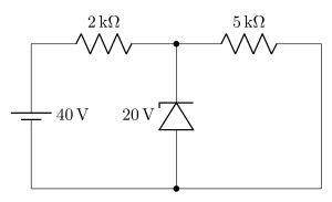
- AP EAPCET 2025Set eng-2025-05-21-FN1 markMCQQ.A Zener diode of breakdown voltage 20 V is connected as shown in the given circuit. The current through Zener diode is [FIGURE] (a circuit with a 40 V battery in series with a 2kΩ resistor connecting to a node; from that node a Zener diode of breakdown voltage 20 V is connected to the bottom rail, in parallel with a 5kΩ resistor also connected from the node to the bottom rail) (A) 10 mA (B) 4 mA (C) 6 mA (D) 8 mA
›Reveal solutionSolution
A Zener regulator problem: the diode clamps the node to its breakdown voltage (20 V); apply KCL at that node to find the diode current — 6 mA.
Concept and Intuition
A Zener diode used as a voltage regulator, when reverse-biased into breakdown, holds a nearly constant voltage across itself (its rated breakdown voltage) regardless of the current through it, as long as some minimum current flows. Here the node between the 2 kΩ and 5 kΩ resistors is held at 20 V by the Zener (since the 40 V source is well above the 20 V breakdown, the diode does break down). The 5 kΩ resistor is connected in parallel with the Zener between this node and the bottom rail (ground), while the 2 kΩ resistor feeds current into the node from the 40 V source.
Step-by-Step Solution
- Since the source (40 V) exceeds the Zener breakdown voltage (20 V), the diode conducts in breakdown and clamps the node voltage to V=20 V.
- Current supplied through the 2 kΩ resistor (from source to node):
Itotal=2kΩ40−20=200020=10 mA
- Current through the 5 kΩ resistor (node to ground, in parallel with the Zener):
I5k=5kΩ20=500020=4 mA
- By Kirchhoff's Current Law at the node, the remaining current flows through the Zener:
IZ=Itotal−I5k=10−4=6 mA
Common Mistakes
- Assuming the full source current flows through the Zener, ignoring the parallel 5 kΩ path.
- Using 40 V instead of the clamped 20 V to compute the current through the 5 kΩ resistor.
✓Final answerThe correct option is (C) — 6 mA.
ANSWER: C
- AP EAPCET 2025Set eng-2025-05-21-AN1 markMCQQ.A transistor works as an amplifier when (A) emitter-base junction is forward biased and base-collector junction is reverse biased (B) both emitter-base and base-collector junctions are forward biased (C) both emitter-base and base-collector junctions are reverse biased (D) emitter-base junction is reverse biased and base-collector junction is forward biased
›Reveal solutionSolution
Amplifier action in a transistor requires forward bias at the emitter-base junction and reverse bias at the base-collector junction.
Concept and Intuition
A transistor works as an amplifier only in the "active region." In this mode, the emitter-base (EB) junction is forward biased so that majority carriers are injected in large numbers from the emitter into the thin, lightly-doped base. The base-collector (BC) junction is reverse biased so that these carriers, having diffused across the base, are swept efficiently into the collector by the junction's field, producing a large collector current controlled by a small base current — the basis of current/voltage gain.
Step-by-Step Solution
- Recall the three transistor operating regions: cutoff (both junctions reverse biased), saturation (both forward biased), and active (EB forward, BC reverse).
- Amplification (linear, proportional gain) only happens in the active region.
- So the correct bias condition is: EB forward biased, BC reverse biased.
Common Mistakes
- Confusing this with saturation (both forward) which is used for switching "on", not amplification.
- Confusing this with cutoff (both reverse) which is switching "off".
✓Final answerThe correct option is (A) — emitter-base junction is forward biased and base-collector junction is reverse biased.
ANSWER: A
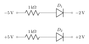
- AP EAPCET 2025Set ap-2025-05-19-AN1 markMCQQ.If two diodes D1 and D2 are connected as shown in the figure, then [FIGURE] (two parallel branches: the upper branch has −5V connected through a 1 kΩ resistor to diode D1 (pointing rightward, anode on the left) leading to −2V; the lower branch has +5V connected through a 1 kΩ resistor to diode D2 (pointing rightward, anode on the left) leading to +2V) (A) both the diodes D1 and D2 are forward biased. (B) both the diodes D1 and D2 are reverse biased. (C) diode D1 is forward biased and diode D2 is reverse biased. (D) diode D1 is reverse biased and diode D2 is forward biased.
›Reveal solutionSolution
The key idea is to check the voltage across each diode: a diode is forward biased when its anode is at a higher potential than its cathode. For D₁, the anode is at -5 V and the cathode at -2 V (reverse bias); for D₂, the anode is at +5 V and the cathode at +2 V (forward bias). Thus the correct option is (D).
Concept and Intuition: P‑N Junction Biasing
A diode conducts only when its anode is more positive than its cathode — this is forward bias. If the anode is more negative than the cathode, the diode is reverse biased and blocks current (ideally). The trick in this problem is that the resistors don’t change the polarity of the voltages applied to the diode terminals; they only limit current once the diode turns on. So we simply compare the voltages at the two ends of each diode.
Step‑by‑Step Reasoning
-
Identify the terminals of each diode
Both diodes are drawn with the triangle pointing right: the flat side (cathode) is on the right, the pointed side (anode) is on the left.
- For D₁: anode is connected to the –5 V source (through a 1 kΩ resistor), cathode is connected to the –2 V node.
- For D₂: anode is connected to the +5 V source (through a 1 kΩ resistor), cathode is connected to the +2 V node.
-
Determine the bias condition for D₁
- Anode voltage: –5 V
- Cathode voltage: –2 V
- Voltage across D₁ (anode minus cathode): VD1=(−5)−(−2)=−3V Since the anode is more negative than the cathode, D₁ is reverse biased.
-
Determine the bias condition for D₂
- Anode voltage: +5 V
- Cathode voltage: +2 V
- Voltage across D₂: VD2=(+5)−(+2)=+3V Since the anode is more positive than the cathode, D₂ is forward biased.
-
Match to the options
- D₁ reverse biased, D₂ forward biased → option (D).
Watch outA common mistake is to think the resistor “drops” voltage before the diode, so the diode sees a different voltage. But until the diode conducts, no current flows, so no voltage drop occurs across the resistor — the full source voltage appears at the diode’s anode. Even after conduction, the polarity of the applied voltage determines the bias direction.
TipFor ideal diodes in DC circuits, ignore the resistor when deciding bias — just compare the voltages at the two ends of the diode. The resistor only matters for current calculations after you know the diode is on.
✓Final answerThe correct option is (D).
ANSWER: D
-
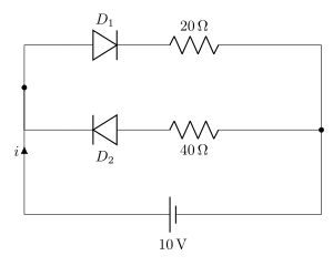
- AP EAPCET 2025Set ap-2025-05-19-FN1 markMCQQ.Two diodes with zero resistance in forward bias and infinite resistance in reverse bias are connected to a battery as shown in the circuit. Then the value of current 'i' is [FIGURE] (a circuit with a 10 V battery; the current i flows from the battery into two parallel branches — the upper branch has diode D1 (pointing so as to conduct in the direction of current flow) in series with a 20 Ω resistor, and the lower branch has diode D2 (pointing in the opposite direction) in series with a 40 Ω resistor; both branches reconnect back to the battery) (A) zero (B) 0.5 A (C) 0.4 A (D) 0.75 A
›Reveal solutionSolution
The key idea is that only the forward‑biased diode conducts; the reverse‑biased diode acts as an open circuit. Here, D₁ is forward‑biased and D₂ is reverse‑biased, so current flows only through the 20 Ω resistor, giving i=10V/20Ω=0.5A. The correct option is (B).
1. Understanding the diode model
The problem states that each diode has zero resistance when forward‑biased (ideal short circuit) and infinite resistance when reverse‑biased (ideal open circuit). This is the simplest possible diode model — no threshold voltage, no internal resistance. So a diode either acts like a wire (if current can flow in the direction of its arrow) or like a broken wire (if current tries to flow opposite to its arrow).
2. Determining the bias of each diode
The battery’s positive terminal is at the top (since current i flows upward out of the battery into the junction). Let’s trace the possible paths:
-
Upper branch: Diode D₁ points rightward (arrow from left to right). Current coming from the battery enters the left end of the upper branch. For D₁ to conduct, current must flow left‑to‑right through it — that is exactly the direction the battery pushes. So D₁ is forward‑biased → acts as a short circuit (0 Ω).
-
Lower branch: Diode D₂ points leftward (arrow from right to left). Current from the battery enters the left end of the lower branch. To go through D₂, current would have to flow left‑to‑right, but the diode’s arrow points the opposite way. So D₂ is reverse‑biased → acts as an open circuit (infinite resistance).
Watch outA common mistake is to think both diodes might conduct because they are in parallel. But the orientation of D₂ is opposite to the driving voltage, so it blocks completely. Never assume parallel branches both work — check each diode’s bias relative to the applied voltage polarity.
3. Simplifying the circuit
With D₁ as a short and D₂ as an open, the circuit reduces to:
- A 10 V battery connected directly to a single 20 Ω resistor (the upper branch). The lower branch is completely disconnected.
Thus the total current i is simply:
i=RV=20Ω10V=0.5A
4. Checking the options
- (A) zero — would require both diodes to block, but D₁ conducts.
- (B) 0.5 A — matches our calculation.
- (C) 0.4 A — would arise if both branches conducted in parallel (10 V / 25 Ω), but D₂ blocks.
- (D) 0.75 A — no plausible combination gives this.
TipIf you ever see a circuit with ideal diodes and a single battery, first identify which diodes are forward‑biased by the battery’s polarity. Then replace those with wires and the others with open circuits. The rest is just Ohm’s law.
✓Final answerThe correct option is (B).
ANSWER: B
-
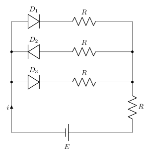
- AP EAPCET 2025Set ap-2025-05-20-AN1 markMCQQ.If the junction diodes D1,D2 and D3 in the given circuit are ideal, then the value of current 'i' in the circuit is (For ideal diode forward biased resistance is zero and reverse biased resistance is infinity) [FIGURE] (a circuit with three parallel branches between two vertical rails: the top branch has diode D1 oriented forward, in series with a resistor R; the middle branch has diode D2 oriented in reverse, in series with a resistor R; the bottom branch has diode D3 oriented forward, in series with a resistor R; all three branches join the right rail, which also has a resistor R connecting down to the bottom rail; a battery E and the current i complete the circuit at the bottom left) (A) 3R2E (B) 2RE (C) RE (D) zero
›Reveal solutionSolution
The key idea is that ideal diodes act as perfect switches: forward‑biased → short circuit, reverse‑biased → open circuit.
Only the two forward‑biased diodes (D1 and D3) conduct, while D2 is reverse‑biased and blocks.
The resulting equivalent circuit is two parallel resistors R (from D1 and D3) in series with the bottom resistor R and the battery E.
The total current is i=3R2E, so the correct option is (A).
Concept and Intuition
An ideal diode is a one‑way valve for current:
- Forward bias (anode voltage > cathode voltage) → zero resistance (short circuit).
- Reverse bias (anode voltage < cathode voltage) → infinite resistance (open circuit).
In this circuit, the battery E sets the polarity. The left‑hand node is at a higher potential than the right‑hand node (because the battery’s positive terminal is at the bottom left, and current flows upward into the left node). So we check each diode’s orientation relative to this voltage drop.
Step‑by‑Step Reasoning
-
Identify the voltage polarity across the circuit
The battery E has its positive terminal at the bottom‑left corner. Current i flows upward into the left node, so the left node is at a higher potential than the right‑hand vertical wire. Therefore, the voltage across any branch from left to right is positive (left is +, right is –).
-
Determine the bias of each diode
- D1 (top branch): Its triangle points right (anode on left, cathode on right). Left is higher potential → forward bias → short circuit.
- D2 (middle branch): Its triangle points left (anode on right, cathode on left). Left is higher potential → cathode is at higher voltage than anode → reverse bias → open circuit.
- D3 (bottom branch): Same orientation as D1 (anode left, cathode right) → forward bias → short circuit.
-
Replace diodes with their ideal equivalents
- D1 and D3 become wires (0 Ω).
- D2 becomes a break (infinite resistance).
The circuit now simplifies: two parallel branches (each with a resistor R in series with a short) connect the left node to the right node. The middle branch is absent.
-
Simplify the parallel resistors
The two conducting branches each contain one resistor R. They are in parallel between the left node and the right vertical wire.
Equivalent resistance of two R in parallel:
Rparallel=R+RR⋅R=2R.
-
Add the bottom resistor
The right vertical wire connects down to a fourth resistor R (the one drawn vertically at the bottom right). This resistor is in series with the parallel combination because the current must flow from the left node through the parallel resistors to the right wire, then down through the bottom R to the battery’s negative terminal.
Total resistance seen by the battery:
Rtotal=Rparallel+R=2R+R=23R.
- Apply Ohm’s law The battery E drives current i through this total resistance:
i=RtotalE=23RE=3R2E.
Watch outA common mistake is to think all three diodes conduct or that the middle diode somehow “reverses” the current. Remember: an ideal diode in reverse bias is an open circuit — no current flows through D2 at all.
TipWhen diodes are ideal, always replace forward‑biased ones with a wire and reverse‑biased ones with a gap. Then redraw the circuit — it becomes a simple resistor network.
✓Final answerThe correct option is (A).
ANSWER: A
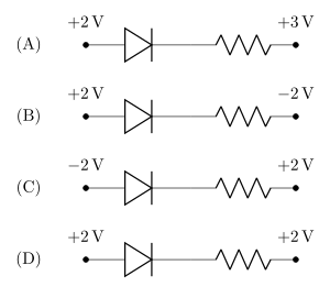
- AP EAPCET 2025Set eng-2025-05-26-AN1 markMCQQ.In the given options, the diode that is forward biased is (A) [FIGURE] (a diode in series with a resistor, connecting a terminal at +2 V through the diode (arrow pointing right, toward the resistor) and resistor to a terminal at +3 V) (B) [FIGURE] (a diode in series with a resistor, connecting a terminal at +2 V through the diode (arrow pointing right) and resistor to a terminal at -2 V) (C) [FIGURE] (a diode in series with a resistor, connecting a terminal at -2 V through the diode (arrow pointing right) and resistor to a terminal at +2 V) (D) [FIGURE] (a diode in series with a resistor, connecting a terminal at +2 V through the diode (arrow pointing right) and resistor to a terminal at +2 V)
›Reveal solutionSolution
A diode conducts (is forward biased) only when its anode (p-side) sits at a higher potential than its cathode (n-side); checking all four terminal pairs, only the +2V→−2V branch satisfies this.
Concept and Intuition
The diode symbol's triangle points in the direction conventional current is allowed to flow when forward biased — from anode (p-side, the flat triangle base) to cathode (n-side, the bar). For that current to actually flow in a circuit connecting two fixed-potential terminals through the diode and a resistor, the external circuit must be 'pushing' current in that same direction, which happens precisely when the anode-side terminal is at a higher potential than the cathode-side terminal. If the cathode side is higher (or equal), the diode blocks conduction (reverse biased or no bias).
Step-by-Step Solution
- In every option, the diode's arrow points right, so the anode connects to the left terminal and the cathode (through the resistor) connects to the right terminal.
- Option (A): left (anode) =+2 V, right (cathode) =+3 V. Anode is at a lower potential than cathode ⇒ reverse biased.
- Option (B): left (anode) =+2 V, right (cathode) =−2 V. Anode is at a higher potential than cathode (by 4 V) ⇒ forward biased — current can flow.
- Option (C): left (anode) =−2 V, right (cathode) =+2 V. Anode is lower than cathode ⇒ reverse biased.
- Option (D): both terminals at +2 V — no potential difference, so there's no driving force for current; the diode carries no current (not meaningfully forward biased).
- Only option (B) has the anode at higher potential, so it is the forward-biased diode.
Common Mistakes
- Forgetting which end of the arrow/bar is the anode vs cathode.
- Assuming a larger magnitude of voltage (like +3 V) automatically means forward bias, rather than checking the sign of (anode potential − cathode potential).
✓Final answerThe correct option is (B) — the diode connecting +2 V (anode side) to −2 V (cathode side).
ANSWER: B
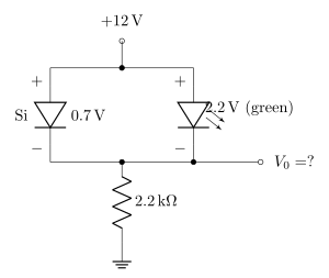
- AP EAPCET 2024Set eng-2024-05-19-AN1 markMCQQ.The voltage Vo in the network shown is [FIGURE] (a circuit with a +12 V supply feeding a node from which two branches drop down in parallel: one branch is a silicon diode 'Si' with a 0.7 V drop, the other is a green LED with a 2.2 V drop; both branches reconnect at a common lower node, which then connects through a 2.2 kΩ resistor to ground, with the output Vo taken at the node between the diode branches and the resistor) (A) Vo=11.3 V (B) Vo=9.8 V (C) Vo=12.0 V (D) Vo=0.7 V
›Reveal solutionSolution
This tests the behaviour of two diodes with different forward-voltage drops connected in parallel between a supply and a common node: the lower-threshold diode "wins" and clamps the node voltage, while the higher-threshold diode stays off.
Concept and Intuition
When two diodes (with different fixed forward voltages) are connected in parallel, in the same forward direction, between a fixed supply and a common node, only one of them can actually conduct at a time in this idealized picture — whichever one needs the smaller forward voltage reaches its "on" condition first as the node voltage builds up. Once that diode conducts, it clamps the node at (supply − its own drop); if the resulting voltage across the other diode is less than the other diode's own threshold, that diode stays off, which is self-consistent.
Step-by-Step Solution
- Assume the silicon diode (drop 0.7 V) conducts: node voltage Vo=12−0.7=11.3 V.
- Voltage now available across the LED branch =12−Vo=12−11.3=0.7 V.
- The LED needs 2.2 V forward drop to conduct — but only 0.7 V is available across it, which is insufficient, so the LED indeed stays OFF. This is self-consistent.
- (Check the opposite assumption: if the LED conducted instead, Vo would be 12−2.2=9.8 V, leaving 2.2 V across the Si diode branch — well above the Si diode's 0.7 V threshold, meaning the Si diode WOULD also conduct and pull the node up, contradicting the assumption. So this scenario is inconsistent.)
- Hence the only self-consistent solution is: Si diode conducts, LED is off, and Vo=11.3 V.
Common Mistakes
- Assuming the resistor value (2.2 kΩ) matters for this DC-steady-state voltage — it doesn't, since Vo is fixed entirely by whichever diode conducts (the resistor only sets the current, not asked here).
- Averaging the two diode drops or assuming both diodes conduct simultaneously, which is not electrically consistent here.
✓Final answerThe correct option is (A) — Vo=11.3 V.
ANSWER: A
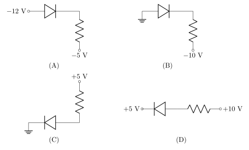
- AP EAPCET 2024Set eng-2024-05-23-FN1 markMCQQ.In the diodes shown in the diagrams, which one is reverse biased? (A) [FIGURE] (a diode conducting from a −12 V node toward a resistor connected to a −5 V node) (B) [FIGURE] (a diode conducting from a grounded node toward a resistor connected to a −10 V node) (C) [FIGURE] (a +5 V node connects through a resistor down to a node that connects through a diode to ground, the diode conducting toward ground) (D) [FIGURE] (a diode conducting from a +5 V node through a resistor to a +10 V node)
›Reveal solutionSolution
Reverse bias means cathode more positive than anode; only option A has Vcathode(−5V)>Vanode(−12V).
Concept and Intuition
For a p-n junction diode, forward bias requires the anode (p-side, the triangle) to be at a higher potential than the cathode (n-side, the bar); reverse bias is the opposite. To test each circuit, compare the potential the anode side is tied to against the potential the cathode side is tied to (in reverse bias no current flows, so each terminal simply sits at its source potential).
Step-by-Step Solution
- Option A: anode at −12V, cathode toward −5V. Cathode potential (−5)> anode potential (−12) by 7V → reverse biased.
- Option B: anode at 0V (ground), cathode toward −10V. Anode (0)> cathode (−10) → forward biased.
- Option C: the diode conducts toward ground, so its anode faces the +5V side and cathode is at ground; anode (+5)> cathode (0) → forward biased.
- Option D: cathode at +5V, anode toward +10V; anode (+10)> cathode (+5) → forward biased.
- Only option A has the cathode at the higher potential, so it is the reverse-biased diode.
Common Mistakes
- Judging bias from the magnitude of the voltage rather than which side is more positive — for negative rails, the less-negative node is the higher potential.
- Confusing anode (triangle) and cathode (bar); the bar marks the n-side.
- Assuming a resistor changes the bias decision — in the blocked state no current flows, so there is no drop across it.
✓Final answerThe correct option is (A) — anode at −12V, cathode toward −5V (cathode more positive), so it is reverse biased.
ANSWER: A
NoteThis solution was worked out by our team and cross-checked by a second independent solve. The official answer key for this question could not be confirmed, so please cross-verify with the official paper where possible.
- AP EAPCET 2023Set ap-2023-05-23-FN1 markMCQQ.When the voltage applied across a reverse biased p-n junction diode is increased then, the diffusion current (A) increases (B) decreases (C) first increases and then decreases (D) remains constant
›Reveal solutionSolution
Increasing reverse bias raises the junction's potential barrier, which suppresses majority-carrier diffusion across the junction — so the diffusion current decreases (while the minority-carrier drift/saturation current stays roughly constant).
Concept and Intuition
A p-n junction diode carries two competing current components: diffusion current (majority carriers moving down their concentration gradient, dominant in forward bias) and drift current (minority carriers swept across by the built-in/applied field, roughly voltage-independent and small). Reverse bias adds to the built-in potential barrier, making the barrier taller. A taller barrier means fewer majority carriers have enough energy to diffuse across it, so the diffusion current — which is already tiny under reverse bias — shrinks even further as the reverse voltage is increased. The reverse (drift) current, by contrast, is limited by the rate of thermal generation of minority carriers, not by the barrier height, so it stays essentially constant (the reverse saturation current).
Step-by-Step Solution
- Under reverse bias, the applied voltage adds to the internal barrier potential, widening the depletion region and raising the barrier height.
- Diffusion current depends exponentially on the barrier height (fewer carriers have sufficient thermal energy to surmount a taller barrier).
- As reverse voltage increases, the barrier keeps rising, so the diffusion current keeps decreasing (approaching essentially zero).
- Meanwhile the drift current (driven by the field sweeping minority carriers across) stays roughly constant, since it is limited by minority-carrier generation rate, not barrier height.
Common Mistakes
- Confusing diffusion current with the total (or drift) current, which does not significantly change with reverse voltage (this is the "saturation" behaviour).
- Assuming reverse bias increases all currents because "more voltage is applied" — but the direction of the current matters, and it's specifically the diffusion component that is suppressed.
✓Final answerThe correct option is (B) — decreases.
ANSWER: B
- AP EAPCET 2023Set eng-2023-05-18-FN1 markMCQQ.A reverse biased zener diode when operated in the breakdown region works as (A) an amplifier (B) an oscillator (C) a voltage regulator (D) a rectifier
›Reveal solutionSolution
This tests the key application of Zener breakdown: a near-flat V–I curve in breakdown lets the diode hold a fixed output voltage, so it is used as a voltage regulator.
Concept and Intuition
A Zener diode is a heavily-doped p-n junction. In forward bias it behaves like an ordinary diode. In reverse bias, once the applied voltage reaches the Zener (breakdown) voltage VZ, the reverse current rises very sharply while the voltage across the diode stays essentially constant at VZ. That "constant voltage even though current changes a lot" behaviour is precisely the property a voltage regulator needs.
Step-by-Step Solution
- Bias the Zener diode in reverse with a series resistor from an unregulated supply.
- As long as the reverse voltage exceeds VZ, the diode conducts heavily and clamps the voltage across itself at VZ.
- Any excess voltage (supply fluctuation, load current change) is dropped across the series resistor, not the diode.
- The load connected in parallel with the diode therefore always sees the constant voltage VZ — this is the standard Zener voltage-regulator circuit.
Common Mistakes
- Confusing Zener breakdown (controlled, non-destructive, exploited for regulation) with avalanche breakdown in an ordinary junction diode (which is destructive if not limited).
- Thinking a bare diode can "amplify" or "oscillate" — amplification and oscillation need an active three-terminal device (transistor) with proper biasing/feedback, not a two-terminal passive diode.
✓Final answerThe correct option is (C) — a voltage regulator.
ANSWER: C
- AP EAPCET 2022Set eng-2022-07-07-FN1 markMCQQ.Consider the following statements Statement (A): The resistance of an ideal diode in forward biased condition is zero. Statement (B): In a half wave rectifier, the load current flows only for every half cycle of the input signals. Statement (C): In the breakdown region, a zener diode behaves as a constant voltage source. (A) A, B & C are all true. (B) A, B true but C is false (C) A, C true but B is false (D) B, C true but A is false
›Reveal solutionSolution
This checks three foundational facts from semiconductor devices (ideal diode resistance, half-wave rectification, Zener regulation) — all three given statements are correct.
Concept and Intuition
An ideal diode is modelled as a perfect one-way switch: zero resistance (a short circuit) when forward biased, and infinite resistance (an open circuit) when reverse biased. A half-wave rectifier uses a single diode so that current can flow through the load only during the half-cycle for which the diode is forward biased, being cut off during the other half. A Zener diode is designed to operate reverse biased in its breakdown region, where the voltage across it stays essentially constant over a wide range of currents — this is exactly the property exploited in voltage-regulator circuits.
Step-by-Step Solution
- (A) Ideal diode, forward biased ⇒ acts as a closed switch with zero resistance. True.
- (B) Half-wave rectifier ⇒ diode conducts only during the half-cycle where it is forward biased; load current exists only for every alternate half-cycle of the input. True.
- (C) Zener diode in breakdown (reverse) region ⇒ voltage across it is nearly constant regardless of current variations, behaving like a constant-voltage source. True.
- Since A, B, and C are all independently verified as true statements, the combined answer is that all three are true.
Common Mistakes
- Thinking an ideal diode has some small nonzero forward resistance (that's a real, not ideal, diode).
- Confusing half-wave with full-wave rectification (full-wave conducts during both half-cycles, using two diodes or a bridge).
- Forgetting that Zener regulation specifically relies on the breakdown (reverse) region, not forward bias.
✓Final answerThe correct option is (A) — A, B & C are all true.
ANSWER: A
- AP EAPCET 2021Set ap-2021-09-06-FN1 markMCQQ.Considering the junction diode to be ideal, find the value of current flowing through AB [FIGURE] (a circuit diagram: point A at +4 V, connected through an ideal junction diode oriented pointing from A toward B, in series with a 1 kΩ resistor, to point B at -6 V) (A) 10−2A (B) 10−1A (C) 10−3A (D) 0A

›Reveal solutionSolution
The key idea is to check whether the diode is forward-biased or reverse-biased by comparing the voltage at its anode (+4 V) to its cathode (-6 V). Since the anode is at a higher potential, the ideal diode acts as a short circuit, and the current through the 1 kΩ resistor is simply the total voltage drop (10 V) divided by the resistance, giving 10 mA = 10−2 A. The correct option is (A).
-
Understand the circuit and the diode orientation
The diode’s triangle (anode) is connected to point A at +4 V, and its bar (cathode) is connected through the resistor to point B at -6 V. For an ideal diode, current flows only when the anode voltage is higher than the cathode voltage — this is called forward bias. If the anode is lower, the diode is reverse-biased and blocks all current.
-
Check the bias condition
Anode voltage = +4 V, cathode voltage = -6 V.
Since +4 V > -6 V, the diode is forward-biased.
For an ideal diode in forward bias, it acts like a perfect conductor (zero voltage drop, zero resistance). So the diode is effectively a wire.
-
Simplify the circuit
With the diode replaced by a short circuit, the circuit becomes:
Point A (+4 V) → short → 1 kΩ resistor → Point B (-6 V).
The total voltage across the resistor is the difference between the two points:
Vtotal=4V−(−6V)=10V.
- Apply Ohm’s law The resistor is 1 kΩ = 1000 Ω.
I=RV=1000Ω10V=0.01A=10−2A.
- Match with the options 10−2 A corresponds to option (A).
Watch outA common mistake is to think the diode is reverse-biased because one terminal is negative. But the bias depends on the relative voltages: here the anode is more positive than the cathode, so it’s forward-biased.
TipWith ideal diodes, always check the polarity: if the anode is at a higher voltage than the cathode, treat it as a wire; otherwise, treat it as an open circuit.
✓Final answerThe correct option is (A).
ANSWER: A
-
🎓Unlock everything free for 14 days
- ✓Full step-by-step solutions
- ✓Concept-first explanations
- ✓Methods, shortcuts & mistakes
- ✓PYQ mapping + timed mock tests
Full access for 14 days. No credit card required.