Physics · Ch 3 — Motion in a Plane
Projectile Motion
Projectile Motion
Projectile Motion
When an object is thrown or projected into the air and continues in flight under the influence of gravity alone, it is called a projectile. A cricket ball, a football, a baseball, or even a stone thrown from a cliff — all are projectiles once they leave the thrower's hand and are acted upon only by gravity (we neglect air resistance throughout this discussion).
The key insight, first stated by Galileo in 1632, is that projectile motion is the combination of two independent motions happening simultaneously: a horizontal motion with constant velocity (no acceleration) and a vertical motion with constant acceleration due to gravity. These two components do not interfere with each other.
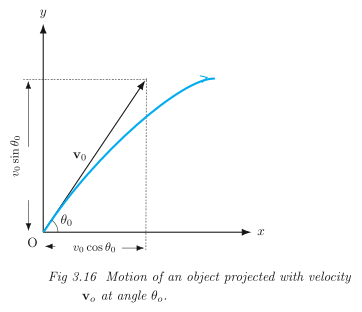
We set up our coordinate system with the x-axis horizontal and the y-axis vertical. The projectile is launched from the origin with an initial speed at an angle measured from the positive x-axis. The acceleration is purely vertical and downward:
The components of the initial velocity are:
The independence of horizontal and vertical motions means we can treat the x-motion and y-motion as two separate one-dimensional problems. This is the central idea that makes analysing projectiles straightforward.
Position and Velocity at Any Time
Starting from the general equations for motion with constant acceleration (Eq. 3.34b from the previous section), and taking the initial position as the origin (), we get:
The velocity components at any time follow from the constant-acceleration velocity equations:
Notice that never changes — the horizontal component of velocity remains constant throughout the flight. Only the vertical component changes, exactly as it would for an object in free fall.
Equation of the Path (Trajectory)
To find the shape of the path, we eliminate time between the expressions for and . From , we have:
Substitute this into :
Since , , and are constants, this is of the form , where and . This is the equation of a parabola. The path of a projectile is therefore a parabola.
The negative sign on the term tells us the parabola opens downward — the projectile rises, reaches a peak, and then falls back to the ground.
Time of Maximum Height
At the highest point of the trajectory, the vertical velocity becomes zero for an instant. Let be the time to reach maximum height. Setting :
Time of Flight
The total time the projectile remains in the air, , is found by setting (the projectile returns to its launch level):
Factor out :
The solution corresponds to the launch instant. The other solution gives:
Notice that — the time to go up equals the time to come down, as expected from the symmetry of the parabola.
Maximum Height
The maximum height is the y-coordinate at time . Substitute into the equation for :
Horizontal Range
The horizontal range is the distance travelled along the x-direction during the total time of flight :
Using the trigonometric identity :
Maximum Range
For a fixed launch speed , the range is maximum when is maximum, i.e., when . This occurs when , or:
The maximum possible horizontal range is therefore:
…
Drawn by us to help you understand the concept clearly, and verified to make sure it's accurate. For exams, practice from your NCERT textbook's own diagram.
The figure is the standard launch diagram for projectile motion. It shows an – coordinate system with the origin at the point of projection. From , a curved parabolic path rises to a maximum height and then falls back to the -axis. The initial velocity vector is drawn as an arrow from at an angle above the positive -axis. Two perpendicular dashed arrows from the tail of show its rectangular components: a horizontal component along the -axis and a vertical component along the -axis. A single downward arrow labelled is placed near the path, indicating that the only acceleration is constant gravity acting vertically downward.
The physical idea is that the motion separates cleanly into two independent parts. Horizontally, there is no acceleration, so the -component of velocity stays constant at . Vertically, the acceleration is constant at , so the -component of velocity changes uniformly from its initial value to zero at the peak, then to negative values on the descent. The parabolic shape of the trajectory is the result of combining this uniform horizontal motion with uniformly accelerated vertical motion.
From this figure the textbook develops the core equations of projectile motion. The position at any time is given by
The velocity components are
The time of flight (when again) is , the maximum height (when ) is , and the horizontal range is . …
Drawn by us to help you understand the concept clearly, and verified to make sure it's accurate. For exams, practice from your NCERT textbook's own diagram.
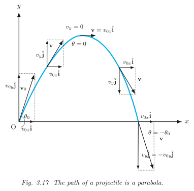
Fig. 3.17 is a single plot of the projectile’s path — the familiar curved arc — drawn on a standard – coordinate grid. The horizontal axis is labelled (range) and the vertical axis (height). The curve itself is a smooth, symmetric parabola that starts at the origin , rises to a maximum height, then falls back to the -axis at the landing point.
The key visual elements are the velocity vectors drawn at three distinct moments: at launch, at the highest point, and just before landing. At the launch point, the initial velocity is shown as an arrow making an angle with the horizontal. This arrow is resolved into two perpendicular components: a horizontal component (pointing right along the -axis) and a vertical component (pointing upward). The figure makes clear that the horizontal component stays constant throughout the flight — the arrow for is drawn with the same length at every stage.
At the apex of the parabola, the vertical velocity arrow disappears: only the horizontal component remains, because at the highest point. On the descent, the vertical component reappears but now points downward, labelled . Just before landing, the velocity vector is again at an angle below the horizontal — the same magnitude as the launch velocity but with the vertical component reversed.
The symmetry of the figure is deliberate: the launch and landing velocities are mirror images across the horizontal axis. This reflects the fact that, in the absence of air resistance, the time to rise equals the time to fall, and the speed at any height is the same on the way up and on the way down.
The physical idea the figure teaches is that projectile motion is the superposition of two independent motions: uniform motion along (no acceleration) and uniformly accelerated motion along (acceleration ). The parabolic shape emerges because is a quadratic function of .
The textbook develops the following central formulas from this figure. The initial velocity components are:
At any time , the position coordinates are:
Eliminating gives the equation of the trajectory:
which is of the form — a parabola. Here is the acceleration due to gravity (), is the initial speed, and is the launch angle measured from the horizontal.
A common mistake is to think the horizontal velocity changes. The figure’s constant-length arrows are a visual reminder: stays throughout the entire flight. Only the vertical component changes, and it does so at a constant rate . …