Q.(a) For circuits used for transporting electric power, a low power factor implies large power loss in transmission. Explain.
Power factor () determines what fraction of the supplied current actually delivers power. A low power factor means large reactive current flows in the transmission lines, causing losses without contributing useful work. Adding a capacitor cancels the lagging reactive current, reducing line current and thus transmission losses.
(a) Why low power factor causes large transmission losses
-
What power factor actually means. In an AC circuit, the power factor is the cosine of the phase angle between voltage and current. Only the component of current that is in phase with the voltage — called the active or power component — delivers real power . The perpendicular component is wattless; it sloshes energy back and forth between source and load but does zero net work.
-
The transmission line doesn't care about phase. The wires connecting the power station to the consumer have resistance . The power lost as heat in these lines is , where is the total rms current — both the useful part and the useless part. The utility company must deliver a fixed real power to the customer. From , if is small, the required must be large to maintain the same .
-
The consequence. A larger total current means dramatically larger line losses because loss scales as . For example, if drops from 1.0 to 0.5, the current must double to deliver the same real power, and the loss quadruples. This is why power companies penalise industrial consumers with low power factors — the wasted heat in transmission lines is real money.
A common mistake is to think that only the active current causes heating. In fact, all current flowing through a resistor produces heat, regardless of phase. The wattless component heats the wires just as much as the useful component does.
(b) How a capacitor improves power factor
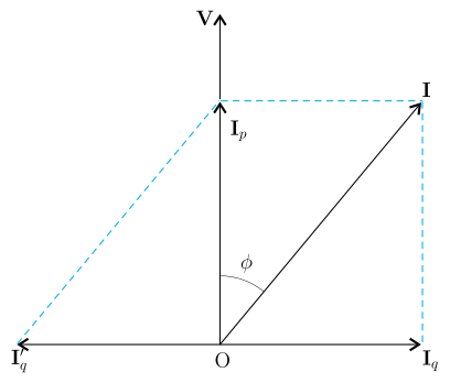
- The geometry of the phasor diagram. Look at Figure 7.15 below. The applied voltage points vertically upward. The load current lags behind by angle (typical for inductive loads like motors and transformers). This current is resolved into:
- — vertical, in phase with (the power component)
- — horizontal, to the right (the lagging wattless component)
-
What a capacitor does. A pure capacitor draws a current that leads the voltage by . In the phasor diagram, this leading current points horizontally to the left — exactly opposite to the lagging . When we connect a capacitor in parallel with the load, the total line current becomes the vector sum of the load current and the capacitor current.
-
Cancelling the reactive component. If we choose the capacitor such that , the horizontal components cancel completely. The net line current becomes purely vertical — in phase with the voltage. The phase angle becomes zero, and . Even partial cancellation (a smaller capacitor) reduces and improves the power factor.
You don't need to make exactly 1. Even raising it from 0.7 to 0.9 cuts the line current by about 22% (since ), which reduces losses by nearly 40%. Power companies often target as a practical optimum.
- Why this reduces transmission losses. After adding the capacitor, the total line current is smaller than the original for the same delivered real power . Since , the reduction in current directly reduces the heat wasted in the transmission lines. The capacitor itself is nearly lossless (ideal capacitors dissipate negligible power), so the improvement comes essentially for free.
For fixed , , and , the loss is inversely proportional to . Halving quadruples the loss.
A low power factor increases transmission losses because the line current must be larger to deliver the same real power, and losses scale as ; adding a capacitor in parallel supplies a leading reactive current that cancels the lagging reactive component of the load current, reducing the total line current and thus the losses.
Unlock everything free for 14 days
- Full step-by-step solutions
- Concept-first explanations
- Methods, shortcuts & mistakes
- PYQ mapping + timed mock tests
Full access for 14 days. No credit card required.