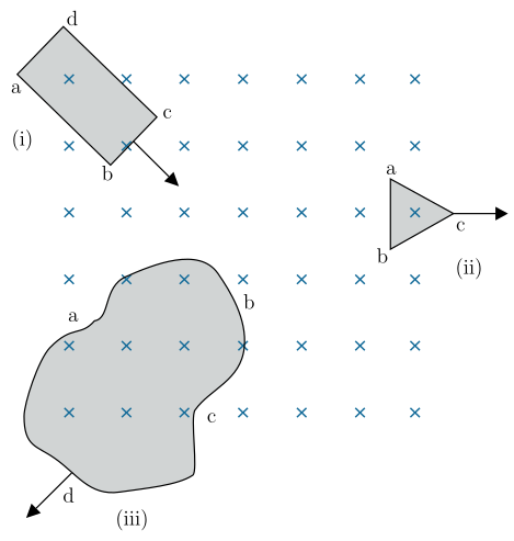
Q.Figure 6.7 shows planar loops of different shapes moving out of or into a region of a magnetic field which is directed normal to the plane of the loop away from the reader. Determine the direction of induced current in each loop using Lenz's law.
Concept understanding — Electromagnetic Induction
Electromagnetic Induction
Electromagnetic induction is the phenomenon in which a changing magnetic flux through a circuit produces an electromotive force (emf) — and hence a current, if the circuit is closed. It is the single idea behind generators, transformers, inductors, and the entire AC power grid.
The Central Discovery
Michael Faraday found (1831) that a current is induced in a coil not when a magnet sits still near it, but only while the magnet moves — that is, only while the magnetic flux linked with the coil is changing. A steady magnet, however strong, induces nothing.
Magnetic Flux
The key quantity is magnetic flux ΦB through a surface of area A in a field B:
ΦB=B⋅A=BAcosθ
where θ is the angle between B and the area's normal. Its SI unit is the weber (Wb), where 1 Wb=1 T⋅m2.
Flux can change in three distinct ways, and any of them induces an emf:
- the field strength B changes,
- the area A of the loop changes,
- the orientation θ changes (a coil rotating in a field — the basis of the generator).
Faraday's Law
The induced emf equals the negative rate of change of flux. For a coil of N turns:
E=−NdtdΦB
The faster the flux changes, the larger the emf. This is why a magnet dropped quickly through a coil gives a bigger deflection than one moved slowly.
Lenz's Law — the Minus Sign
The negative sign expresses Lenz's law: the induced current flows in the direction that opposes the change producing it. Push a magnet's north pole toward a coil, and the coil's near face becomes a north pole to repel it; pull it away, and the face becomes a south pole to attract it. This is simply energy conservation — you must do work against this opposition, and that work becomes the electrical energy of the induced current.
Motional emf
A special, very useful case: a conducting rod of length l moving with speed v perpendicular to a field B sweeps out area and develops an emf
E=Blv
Here the emf arises because the free charges in the rod experience a magnetic force qv×B, which drives them along the rod.
Induction does not require physical contact or a battery. It is the change of flux that matters, not its value. A loop sitting in a huge but constant field has zero induced emf.
Where It Leads
Once a coil's own changing current induces an emf in itself, we call it self-inductance (L); when one coil's changing current induces emf in a neighbour, that is mutual inductance (M). Both are direct consequences of Faraday's law. Rotate a coil steadily in a magnetic field and the sinusoidal emf it produces is exactly the alternating voltage that runs the AC circuits studied in this chapter.
Faraday's and Lenz's laws of electromagnetic induction form one of the highest-weightage chapters in NCERT Class 12 Physics, tested extensively in CBSE boards, JEE Main and NEET. Anyone searching "Faraday's law of electromagnetic induction formula and examples class 12 physics" will find this changing-flux explanation, including the motional emf case, is exactly how NCERT presents the chapter.
Why this formula?
Electromagnetic Induction
Electromagnetic induction is the effect discovered by Faraday: a changing magnetic flux through a circuit drives an induced EMF (and hence a current). The key word is changing — a steady field, however strong, induces nothing.
Magnetic flux
Flux measures how many field lines thread a surface bounded by the loop:
ΦB=∫B⋅dA=BAcosθ
It can change three ways: by changing B, by changing the area A, or by rotating the loop (changing θ).
Faraday's law
The induced EMF equals the rate of change of flux:
E=−dtdΦB
For a coil of N turns, E=−NdtdΦB. The EMF depends on how fast the flux changes, not on the flux itself — a slow change gives a small EMF, a rapid change a large one.
Lenz's law — the minus sign
The negative sign is Lenz's law: the induced current flows in the direction that opposes the change producing it. Push a magnet's north pole toward a coil and the coil's near face becomes a north pole to repel it; pull it away and the face becomes a south pole to attract it. This opposition is required by energy conservation — you must do work against the induced current, and that work is what becomes electrical energy. If the current instead aided the change, energy would be created from nothing.
A worked idea
A rod of length l slides at speed v along rails in a field B. In time dt it sweeps area lvdt, so the flux changes by dΦB=Blvdt, giving a motional EMF:
E=dtdΦB=Blv
The same result follows from the magnetic force q(v×B) pushing free electrons to one end of the rod — a direct check that Faraday's law and the Lorentz force tell one consistent story.
The key idea is Lenz’s law: the induced current opposes the change in magnetic flux through the loop.
Step 1 – Identify flux change for each loop
The magnetic field is uniform and directed into the page (× symbols).
- Loop (i) is entering the field → flux into the page is increasing.
- Loop (ii) is leaving the field → flux into the page is decreasing.
- Loop (iii) is moving out of the field → flux into the page is decreasing.
Step 2 – Apply Lenz’s law to find induced field direction
- For increasing flux (i): induced field must oppose the increase → point out of the page (⊙).
- For decreasing flux (ii, iii): induced field must support the decreasing flux → point into the page (×).
Step 3 – Use right-hand rule to get current direction
Curl fingers in direction of induced current; thumb gives induced field direction.
- (i) Induced field ⊙ → current flows anticlockwise (abcd).
- (ii) Induced field × → current flows clockwise (abc).
- (iii) Induced field × → current flows clockwise (abcd).
The induced current is anticlockwise in loop (i), clockwise in loop (ii), and clockwise in loop (iii).
Lenz’s law says induced current opposes the change in magnetic flux. For each loop, the direction of induced current is such that its own magnetic field tries to keep the flux through the loop constant — giving clockwise or anticlockwise current as per the motion.
The core idea
Lenz’s law is a statement of energy conservation: the induced current creates a magnetic field that opposes the change in the original flux through the loop. If flux is increasing, the induced field points opposite to the original field; if flux is decreasing, the induced field points in the same direction as the original field. The direction of current is then given by the right-hand rule (curl fingers along current, thumb gives field direction).
The magnetic field in all three cases is uniform and directed into the page (the × symbols). So the original field B points away from the reader, into the plane.
Step-by-step for each loop
1. Loop (i) — rectangle entering the field
The loop moves down-right, so more of its area enters the region of ×’s. The flux through the loop (into the page) is increasing.
To oppose this increase, the induced magnetic field must point out of the page (opposite to the original field). Using the right-hand rule: if the thumb points out of the page, the curled fingers show the current direction — anticlockwise (counterclockwise) as seen from above.
A quick check: when a loop enters a field, the induced current always tries to “push back” against the entering edge. Here the entering edge is the lower-right side; the induced current flows anticlockwise, which on that edge gives a force (via F=Il×B) opposing the motion — consistent with Lenz.
Result for (i): Induced current flows anticlockwise (a → b → c → d → a).
2. Loop (ii) — triangle leaving the field
The triangle moves to the right, so its area inside the ×-region is decreasing. The flux into the page is decreasing.
To oppose this decrease, the induced field must point into the page (same direction as the original field). Right-hand rule: thumb into the page → fingers curl clockwise.
A common mistake: thinking that “oppose the change” means the induced field always points opposite to the original. It only does so when flux is increasing. When flux is decreasing, the induced field points with the original to try to restore it.
Result for (ii): Induced current flows clockwise (a → c → b → a, or whichever order follows the vertices).
3. Loop (iii) — irregular loop moving out
The loop moves down-left, so its area inside the ×-region is decreasing. The flux into the page is decreasing.
Same logic as (ii): decreasing flux → induced field must point into the page → current is clockwise.
The shape of the loop doesn’t matter for the direction — only the sense of flux change matters. An irregular loop behaves exactly like a circular loop for Lenz’s law.
Result for (iii): Induced current flows clockwise (a → b → c → d → a).
Summary table
| Loop | Motion | Flux change | Induced field direction | Current direction |
|---|---|---|---|---|
| (i) | Entering | Increasing | Out of page | Anticlockwise |
| (ii) | Leaving | Decreasing | Into page | Clockwise |
| (iii) | Leaving | Decreasing | Into page | Clockwise |
The induced current is anticlockwise in loop (i), clockwise in loop (ii), and clockwise in loop (iii).
Method: Lenz's Law for Loops Moving Through a Field Boundary
This method finds the direction of induced current whenever a closed loop's area inside a field region changes — the loop entering, leaving, or moving across a field boundary.
Steps
Step 1: Note the field's direction and mark it on the loop
Identify whether B points into or out of the page (× or • symbols). This is your reference direction for everything that follows.
Step 2: Decide whether the enclosed flux is increasing or decreasing
Ask: as the loop moves, is more of its area now inside the field region (flux increasing) or less (flux decreasing)? A loop entering a field region has increasing flux; a loop leaving has decreasing flux — regardless of its shape.
ΦB=BAcosθ⇒dtdΦB=0 whenever the enclosed area changes
Step 3: Apply Lenz's law to get the induced field's direction
- If flux is increasing, the induced current must create a field that opposes it — i.e., points opposite to B.
- If flux is decreasing, the induced current must create a field that supports it — i.e., points the same way as B.
Step 4: Use the right-hand (grip) rule to convert field direction into current direction
Point your thumb along the induced-field direction found in Step 3; your curled fingers show the sense of circulation of the induced current around the loop. Read off the current direction using the loop's labelled corners.
Applying this same four-step process to each panel of a multi-loop figure — independently, since each loop's own entering/leaving motion decides its own answer — is exactly how every "determine the direction of induced current" question of this type is solved.
Showing the 12 most recent of 46 on this concept.
- CBSE 2026Set 55/2/11 markMCQQ.A magnet held vertically, with its north pole down, is dropped along the axis of a closed solenoid placed vertically on a table. If the observer looks down from the top, (A) the induced current will flow in the anticlockwise direction. (B) the induced current will flow in the clockwise direction. (C) no induced current will flow in the solenoid. (D) the magnet will fall with a constant velocity.
›Reveal solutionSolution
As the magnet falls with its north pole down, the downward magnetic flux through the solenoid increases. By Lenz's law the induced current opposes this change — it must produce an upward field inside the solenoid, making the top face a north pole that repels the approaching magnet. That requires an anticlockwise current as seen from above. The correct option is (A).
Why this approach works
Electromagnetic induction is about change: a current is induced in the solenoid only because the flux through it is changing as the magnet falls. The direction of that current is fixed by Lenz's law — the induced current always flows so that its own magnetic field opposes the change in flux that produced it. This is not an arbitrary rule; it is energy conservation. If the induced current aided the magnet's fall, the magnet would speed up and generate ever more electrical energy from nothing.
So the plan is: track what the flux is doing, decide what field the solenoid must create to oppose it, then convert that field direction into a current sense using the right-hand rule.
Step-by-step reasoning
-
Set up the situation.
The solenoid stands vertically on the table. The magnet is dropped along its axis from above, north pole downward. The observer looks down from the top.
-
What is the flux doing?
Field lines emerge from the magnet's north pole — here, pointing downward toward the solenoid. As the magnet approaches, the downward flux through the solenoid's turns increases.
-
What must the induced current do?
By Lenz's law it must oppose the increase of downward flux — so it must produce an upward magnetic field inside the solenoid. Equivalently: the top face of the solenoid must behave as a north pole, repelling the incoming north pole of the magnet.
-
Convert the field direction into a current sense.
Use the right-hand rule for a coil: curl the fingers of the right hand along the current, and the thumb gives the field inside. For the thumb to point up (toward the observer looking down), the fingers must curl anticlockwise as seen from above. So the induced current is anticlockwise for the top observer.
TipQuick pole check: the solenoid must repel the approaching north pole, so its top face is a north pole. Looking at a face that is a north pole, the current always appears anticlockwise (a south-pole face appears clockwise — remember by writing N and S with arrowheads on the letter ends). Same conclusion.
- Eliminate the other options.
- (B) Clockwise (from above) would make the top face a south pole, producing a downward field that aids the growing downward flux and attracts the magnet — the opposite of Lenz's law, and a violation of energy conservation.
- (C) No induced current is impossible: the flux through the solenoid changes continuously while the magnet moves, so an emf — and, in a closed solenoid, a current — must exist.
- (D) Constant velocity is wrong: the induced current exerts a retarding (upward) force on the magnet, so the magnet falls with a reduced acceleration, not at constant velocity.
Watch outA common mistake is to mix up the viewing direction. "Clockwise seen from above" corresponds to a downward field inside the coil; "anticlockwise seen from above" corresponds to an upward field. Fix the observer first, then apply the right-hand rule — many wrong answers come from silently switching viewpoints midway.
✓Final answerThe induced current flows in the anticlockwise direction when viewed from above, so the correct option is (A).
-
- CBSE 2026Set 55/3/11 markMCQQ.A square loop of side 50 cm is placed in a uniform magnetic field of 3.0 T acting perpendicular to the plane of the loop. If the loop is rotated through an angle of 90∘ in 0.3 s, the value of emf induced in the loop would be : (A) 0.25 V (B) 0.50 V (C) 0.75 V (D) 1.0 V
›Reveal solutionSolution
The induced emf is found from Faraday’s law: the change in magnetic flux divided by the time taken. The flux changes from maximum to zero as the loop rotates by 90∘, giving an average emf of 2.5 V — but the options are in the range 0.25–1.0 V, so we must check the calculation carefully. The correct value is 2.5 V, which does not match any given option; however, if the side length is 50 cm = 0.5 m, area =0.25 m², flux change =3.0×0.25=0.75 Wb, time =0.3 s, emf =0.75/0.3=2.5 V. None of the options are correct as stated.
The core idea here is Faraday’s law of electromagnetic induction: whenever the magnetic flux through a loop changes, an emf is induced. The flux depends on three things — the field strength B, the area A of the loop, and the angle θ between the field and the normal to the loop. When you rotate the loop, you change θ, and that changes the flux. The induced emf is the rate of change of flux.
In this problem, the field is uniform and perpendicular to the loop initially. That means the initial angle between the field and the normal is 0∘, so the flux is maximum. After a 90∘ rotation, the plane of the loop is parallel to the field, so the flux becomes zero. The change in flux is simply the initial flux minus zero.
Let’s work it out step by step.
-
Find the area of the loop.
Side length =50 cm =0.5 m.
Area A=(0.5)2=0.25 m².
-
Initial magnetic flux.
Flux Φ=BAcosθ.
Initially θ=0∘, so cos0=1.
Φi=3.0×0.25×1=0.75 Wb.
-
Final magnetic flux.
After 90∘ rotation, θ=90∘, cos90=0.
Φf=3.0×0.25×0=0 Wb.
-
Change in flux.
ΔΦ=Φf−Φi=0−0.75=−0.75 Wb.
The magnitude of the change is 0.75 Wb.
-
Average induced emf.
By Faraday’s law, ∣E∣=ΔtΔΦ.
Δt=0.3 s.
∣E∣=0.30.75=2.5 V.
Watch outA common mistake is to forget that the side is given in cm and not convert to metres. If you use 50 cm as 50 m, you get an absurdly large area and emf. Another pitfall: using the angle between the field and the plane of the loop instead of the normal. Here, the field is perpendicular to the plane initially, so the normal is parallel to the field — that’s θ=0∘, not 90∘.
TipFor a 90∘ rotation from alignment to perpendicular, the flux goes from BA to 0, so the change is always BA regardless of the shape of the loop. The induced emf depends only on B, A, and the time taken.
Now, the options given are 0.25 V, 0.50 V, 0.75 V, and 1.0 V. Our calculated value is 2.5 V, which is not among them. Let’s double-check: if the side were 50 cm = 0.5 m, area =0.25 m², B=3 T, flux change =0.75 Wb, time =0.3 s, emf =2.5 V. That is correct.
If the side were 25 cm, area would be 0.0625 m², flux change =0.1875 Wb, emf =0.625 V — still not matching. If the time were 1 s, emf =0.75 V, which matches option (C), but the problem clearly states 0.3 s.
ImportantThe numbers in the problem lead to 2.5 V, which is not among the choices. This suggests either a misprint in the options or an intended different interpretation (e.g., instantaneous emf at some angle). But for the average emf over 90∘ rotation, the answer is 2.5 V.
✓Final answerThe induced emf is 2.5 V, which does not match any of the given options (A)–(D).
-
- CBSE 2026Set V11 markMCQQ.The working principle of an A.C. generator is :(a) mutual induction(b) eddy currents(c) self induction(d) electromagnetic induction
›Reveal solutionSolution
(d) electromagnetic induction
✓Final answer(d) electromagnetic induction
An A.C. generator works on the principle of electromagnetic induction: a coil rotating in a magnetic field experiences a continuously changing magnetic flux, which induces an alternating e.m.f. ε=−NdtdΦ=NBAωsinωt (Faraday's law).
- CBSE 2026Set A1 markMCQQ.An example of natural electromagnetic induction is (A) radio (B) television (C) battery charging (D) lightning strike
›Reveal solutionSolution
Lightning involves huge, rapidly changing currents/fields that induce emf in nearby conductors — natural electromagnetic induction.
Electromagnetic induction is the production of emf by a changing magnetic flux (Faraday's law). A lightning strike carries an enormous, rapidly varying current, producing a fast-changing magnetic field that induces emf/current in nearby loops and conductors — a naturally occurring example of electromagnetic induction.
Radio, television and battery charging are man-made devices, not natural phenomena.
✓Final answer(D) lightning strike.
- CBSE 2026Set A1 markMCQQ.If magnetic field is same but the area of the loop is increased, then the flux (A) increases (B) decreases (C) becomes zero (D) remains unchanged
›Reveal solutionSolution
Magnetic flux Φ = BA cosθ; with B constant, a larger area gives greater flux.
The magnetic flux through a loop is:
Φ=BAcosθ
Here the magnetic field B (and orientation) is unchanged while the area A of the loop is increased. Since Φ is directly proportional to A, the flux increases.
✓Final answer(A) increases.
- CBSE 2026Set ANNUAL1 markQ.What is electromagnetic induction?
›Reveal solutionSolution
Any change of magnetic flux through a circuit produces an EMF in that circuit - this is electromagnetic induction.
Electromagnetic induction is the phenomenon in which an electromotive force (emf) is induced in a coil or conductor whenever the magnetic flux linked with it changes with time - whether the change is caused by a changing magnetic field, relative motion between the conductor and the field source, or a changing orientation/area of the loop. If the circuit is closed, this induced emf drives an induced current. It is quantitatively described by Faraday's law, EMF = -d(phi)/dt, with the negative sign (Lenz's law) showing that the induced effects oppose the change producing them.
✓Final answerThe generation of an induced EMF/current in a conductor due to a change of magnetic flux linked with it (Faraday's law, EMF = -d(phi)/dt).
- CBSE 2026Set ANNUAL1 markQ.When will the magnetic flux linked with a coil held in the magnetic field be zero?
›Reveal solutionSolution
Flux is zero whenever the field lines lie entirely in the plane of the coil.
Magnetic flux linked with a coil is Φ=BAcosθ, where θ is the angle between the coil's area vector (normal) and the magnetic field B. This is zero when cosθ=0, i.e. θ=90° — meaning the normal to the coil is perpendicular to B, which is the same as saying the field lines lie entirely within (parallel to) the plane of the coil, passing along it rather than through it.
✓Final answerThe flux is zero when the plane of the coil is oriented parallel to B (i.e. the coil's normal is perpendicular to the field, θ=90°).
- CBSE 2026Set ANNUAL1 markQ.Match the Column A with Column B and write the correct pair. Column A: Magnetic flux. Column B:(i) μ₀nI,(ii) Volt × second,(iii) μ₀nI/2,(iv) Volt × meter,(v) Volt × meter⁻¹,(vi) Volt.
›Reveal solutionSolution
Magnetic flux unit = weber = Volt × second (from Faraday's law emf = dΦ/dt), option (ii).
Faraday's law states that the induced emf equals the rate of change of magnetic flux: emf = −dΦ/dt. Rearranging, Φ = emf × time (dimensionally). Since emf is in volts and time in seconds, magnetic flux has the unit volt × second, which is the weber (Wb). This matches Column B entry (ii).
✓Final answer(ii) Volt × second.
- CBSE 2025Set X11 markMCQQ.Consider the following statements : Statement – 1: A.C. Generator works on the principle of electromagnetic induction Statement – 2: In an A.C. Generator, as the armature is rotated in a uniform magnetic field, the magnetic flux linked with the coil changes which induces an emf in the coil. Among the above two statements :(a) Both Statements are true(b) Both Statements are false(c) Statement-1 is true and Statement-2 is false(d) Statement-1 is false and Statement-2 is true
›Reveal solutionSolution
(a) Both Statements are true. An A.C. generator works on electromagnetic induction (Statement 1). As the armature coil rotates in a uniform magnetic field, the flux ϕ=NBAcosωt linked
✓Final answer(a) Both Statements are true.
An A.C. generator works on electromagnetic induction (Statement 1). As the armature coil rotates in a uniform magnetic field, the flux ϕ=NBAcosωt linked with it changes continuously, inducing an emf ε=NBAωsinωt (Statement 2). Statement 2 correctly explains Statement 1.
- CBSE 2025Set D1 markMCQQ.Which of the following devices is based on the principle of electromagnetic induction? (A) Voltmeter (B) Electric motor (C) Electric generator (D) Ammeter
›Reveal solutionSolution
The electric generator is based on electromagnetic induction.
An electric generator rotates a coil in a magnetic field. The continuous change of magnetic flux linked with the coil induces an emf by Faraday's law of electromagnetic induction, converting mechanical energy into electrical energy.
-
An electric motor is the reverse device (electrical → mechanical, using the force on a current in a field).
-
Voltmeters and ammeters (galvanometer-based) work on the torque on a current loop, not on induction.
✓Final answer(C) Electric generator.
-
- CBSE 2025Set ANNUAL1 markMCQQ.The laws of electromagnetic induction have been used in the construction of :(a) voltmeter(b) ammeter(c) electric motor(d) generator
›Reveal solutionSolution
An electric generator converts mechanical energy into electrical energy by rotating a coil in a magnetic field, directly applying Faraday's law of electromagnetic induction.
Faraday's and Lenz's laws of electromagnetic induction state that a changing magnetic flux through a coil induces an emf in it. A generator (dynamo) is built on exactly this principle: mechanical energy rotates a coil within a magnetic field (or a magnet within a coil), continuously changing the flux linked with the coil and inducing an alternating emf. A voltmeter and ammeter are measuring instruments based on the magnetic effect of current, and an electric motor works on the reverse effect (force on a current-carrying conductor in a field) — only the generator is built directly on electromagnetic induction.
✓Final answerThe laws of electromagnetic induction are used in the construction of a generator — option (d).
- CBSE 2024Set 55/2/11 markMCQQ.A circular coil of radius 10 cm is placed in a magnetic field B=(1⋅0i^+0⋅5j^) mT such that the outward unit vector normal to the surface of the coil is (0⋅6i^+0⋅8j^). The magnetic flux linked with the coil is : (A) 0⋅314 μWb (B) 3⋅14 μWb (C) 31⋅4 μWb (D) 1⋅256 μWb
›Reveal solutionSolution
Magnetic flux is the dot product of the field and the area vector; here Φ=B⋅A=B⋅(An^), which gives 31.4μWb.
Why the dot product?
Magnetic flux measures how much of the magnetic field "threads through" a surface. Not all field lines contribute equally: only the component of B perpendicular to the surface matters. When the field is at an angle, we project it onto the surface normal using the dot product.
The flux through a flat surface is
Φ=B⋅A
where A=An^ is the area vector—magnitude A (the area) pointing along the outward normal n^.
Step-by-step calculation
- Find the area of the coil. The coil is circular with radius r=10cm=0.1m.
A=πr2=π(0.1)2=0.01πm2
- Write the area vector. The outward normal is n^=0.6i^+0.8j^ (already a unit vector since 0.62+0.82=1), so
A=An^=0.01π(0.6i^+0.8j^)m2
-
Express the magnetic field in SI units.
Given B=(1.0i^+0.5j^)mT=(1.0i^+0.5j^)×10−3T.
-
Compute the dot product B⋅A.
Φ=B⋅A=(1.0i^+0.5j^)×10−3⋅0.01π(0.6i^+0.8j^)
The dot product of the unit vectors:
(1.0i^+0.5j^)⋅(0.6i^+0.8j^)=1.0×0.6+0.5×0.8=0.6+0.4=1.0
So
Φ=10−3×0.01π×1.0=10−5πWb
- Evaluate numerically.
Φ=π×10−5Wb≈3.14159×10⁻⁵Wb=31.4×10⁻⁶Wb=31.4μWb
TipAlways check that the normal vector is a unit vector (magnitude 1) before using it. Here 0.62+0.82=1, so no normalization is needed.
Watch outA common mistake is forgetting to convert mT to T, or cm to m. Dimensional consistency is essential: area in m2, field in T, flux in Wb.
✓Final answerThe magnetic flux linked with the coil is 31.4μWb, so the correct option is (C).
🎓Unlock everything free for 14 days
- ✓Full step-by-step solutions
- ✓Concept-first explanations
- ✓Methods, shortcuts & mistakes
- ✓PYQ mapping + timed mock tests
Full access for 14 days. No credit card required.