Q.A cylindrical bar magnet is rotated about its axis. A wire is connected from the axis and is made to touch the cylindrical surface through a contact. Then
Concept understanding — Motional Emf
Motional Emf
When a conductor moves through a magnetic field, the free charges inside it experience a magnetic force. This force pushes the charges along the conductor, setting up a potential difference across its ends — a motional emf. It is electromagnetic induction viewed from a moving conductor rather than from a changing field.
Origin: the Lorentz force
Consider a straight rod of length l moving with velocity v perpendicular to a uniform field B. Each free charge q feels a force
F=q(v×B)
of magnitude qvB directed along the rod. Charges pile up at the ends until the electric field they create balances the magnetic force. The resulting potential difference — the motional emf — is
ε=Bvl
Consistency with Faraday's law
Let the rod of length l slide along parallel conducting rails, sweeping out a distance x. The enclosed area is A=lx, so the flux is Φ=Blx. Then
ε=−dtdΦ=−Bldtdx=−Blv
The magnitude Bvl matches the Lorentz-force result, showing that the flux rule and the force picture agree.
Worked example
A rod of length 0.4m moves at 5m/s perpendicular to a field of 0.5T:
ε=Bvl=0.5×5×0.4=1V
If the circuit resistance is 2Ω, the induced current is I=ε/R=0.5A.
Force and energy
Once current I flows, the field exerts a retarding force F=BIl on the rod, opposing its motion (Lenz's law). To keep the rod moving at constant speed, an external agent must supply power
P=Fv=BIlv=εI
exactly equal to the electrical power dissipated in the circuit — energy is conserved.
Motional emf arises only from the component of velocity perpendicular to B. Motion parallel to the field produces no emf.
Motional emf, derived from the Lorentz force on charges in a moving conductor, is a key numerical topic within the NCERT Class 12 Physics chapter on electromagnetic induction, tested in CBSE boards and JEE Main. Searches for "motional emf formula and derivation class 12 physics" will find this rod-on-rails explanation, consistent with Faraday's flux rule, matches the NCERT-prescribed derivation.
Why this formula?
Motional EMF: Why the Formula Holds
Let's build this from first principles — understanding the why before the formula.
The Core Idea
Motional EMF arises when a conductor moves through a magnetic field. The key insight: moving charges in a magnetic field experience a magnetic force, which acts like a battery pushing charges around the conductor.
Step 1: The Force on a Moving Charge
A charge q moving with velocity v in a magnetic field B feels the Lorentz magnetic force:
Fm=q(v×B)
This force is perpendicular to both velocity and magnetic field.
Step 2: What Happens Inside a Moving Conductor
Consider a straight metal rod of length L moving with constant velocity v perpendicular to a uniform magnetic field B (pointing into the page).
- Free electrons in the rod are moving with the rod at velocity v.
- Each electron experiences a magnetic force:
Fm=−e(v×B)
(negative sign because electron charge is −e)
- This force pushes electrons along the rod — say, toward one end.
Step 3: Charge Separation Creates an Electric Field
As electrons accumulate at one end, that end becomes negatively charged, leaving the other end positively charged.
- This charge separation creates an internal electric field E inside the rod, pointing from positive to negative end.
- The electric field exerts an opposing force on the electrons:
Fe=−eE
Step 4: Equilibrium — The "Battery" is Formed
Charge keeps moving until the electric force balances the magnetic force:
Fe+Fm=0
−eE−e(v×B)=0
E=−(v×B)
Magnitude-wise (for perpendicular v and B):
E=vB
Step 5: From Electric Field to EMF
The motional EMF E is the work done per unit charge to move a test charge from one end to the other:
E=∫negativepositiveE⋅dl
For a uniform field along the rod of length L:
E=E⋅L=vBL
The Key Formula
Motional EMF for a straight conductor moving perpendicular to B:
E=BLv
Why This Makes Physical Sense
| Quantity | Role |
|---|---|
| B | Stronger magnetic field → larger force on charges |
| L | Longer conductor → more charge separation possible |
| v | Faster motion → larger magnetic force → larger EMF |
Alternative Derivation: Faraday's Law
The same result comes from Faraday's law of induction:
E=−dtdΦB
For a rod of length L moving with speed v through a field B, the area swept per second is Lv, so:
dtdΦB=B⋅dtdA=BLv
Thus:
E=BLv
Both approaches give the same answer — confirming consistency.
Important Exam Points
- Direction: Use Fleming's right-hand rule (generator rule) to find polarity.
- General formula (when v and B are not perpendicular):
E=BLvsinθ
where θ is the angle between v and B.
- EMF is induced only while the conductor moves — stop the motion, stop the EMF.
Bottom line: Motional EMF is simply the magnetic force acting on moving charges inside a conductor, creating a charge separation that acts like a battery. The formula E=BLv is a direct consequence of balancing magnetic and electric forces.
A rotating conducting cylindrical magnet is a homopolar (Faraday) generator.
- The bar magnet is itself a conductor. Its own axial field B threads the metal.
- As the cylinder spins with angular speed ω, every free charge at radius r moves with speed v=ωr across the axial field, so it feels a radial Lorentz force q(v×B). This pushes charge steadily between the axis and the rim.
- The wire (axis contact to a rim contact) closes the circuit, so a constant, one-directional (DC) current flows through it — its sense does not reverse, because the geometry of the field and the motion is unchanging in time.
Note the symmetry argument "field unchanged ⇒ no emf" is a trap: it is a motional emf inside the moving conductor, not a flux change through a fixed loop.
A steady (DC) current flows through the ammeter (NCERT Exemplar option a) — the setup is a homopolar generator.
The spinning conducting magnet acts as a homopolar (Faraday) generator: the axial field acts on the charges of the rotating metal, driving a steady DC current from the axis to the rim through the connecting wire.
The setup
A cylindrical bar magnet, which is a conductor, spins about its own geometric axis. One sliding contact sits on the axis and another on the curved surface; a wire joins them through an ammeter, completing a circuit.
Why a current flows — the motional-emf picture
The magnet's field is (roughly) axial, B∥ axis, and it is carried rigidly with the metal. Consider a free electron in the metal at radius r from the axis. Because the body rotates at angular speed ω, that charge moves with velocity
v=ωrθ^,
i.e. tangentially. It therefore experiences a Lorentz force
F=q(v×B).
With v tangential and B axial, v×B points radially. So charge is driven along the radius, between the axis and the rim. Integrating this force per unit charge from axis (r=0) to rim (r=R) gives a motional emf
ε=∫0R(v×B)⋅dr=∫0RBωrdr=21BωR2,
which is constant in time. A constant emf drives a steady (DC) current I=ε/Rcircuit round the wire.
Why the "symmetry ⇒ no emf" argument fails
It is tempting to say: a cylinder is symmetric about its axis, so rotating it leaves B unchanged everywhere, the flux through the circuit never changes, and hence there is no emf. That reasoning applies to a stationary loop linking a changing flux. Here the emf is motional — it lives in the moving conductor itself, where the flux rule is not the right tool. The charges genuinely move through the field, so a current genuinely flows.
A steady DC current flows in the ammeter — this is a homopolar (Faraday) generator (NCERT Exemplar answer: option a).
Method: Recognising a Motional-EMF (Homopolar Generator) Problem in Disguise
Some induction questions describe a setup where Faraday's flux-rule instinct ("nothing changes, so no current") gives the WRONG answer — because the emf here is motional, generated inside a moving conductor itself, not by a changing flux through a fixed external loop.
Steps
Step 1: Check whether the conductor itself is moving through a field it's rigidly carrying along
If a conducting body is rotating (or translating) with a magnetic field that is fixed relative to the body itself (like a magnetized rotating cylinder), the standard "flux through a stationary loop" argument doesn't apply — the charges inside the moving conductor are the ones experiencing a force.
Step 2: Apply the Lorentz force to a free charge inside the moving conductor
Every free charge q at some point in the moving conductor, with local velocity v, feels
F=q(v×B)
Work out the direction of v (e.g. tangential, for a point rotating about an axis) and the direction of B (e.g. along the axis) to find which way this force pushes charge — this is the origin of the emf, not a changing external flux.
Step 3: Integrate the force per unit charge along the conductor to get the emf
ε=∫(v×B)⋅dr
For a rigid body rotating at constant angular speed with a fixed field geometry, every term inside this integral is constant in time, so ε itself comes out constant — this is the key signature of a steady (DC) motional emf, as opposed to the sinusoidally-varying emf you'd get from a coil rotating relative to an external field.
Step 4: Recognise WHY the naive symmetry argument fails
The trap in this class of question is reasoning "the setup looks unchanged from the outside (same field pattern, same geometry) at every instant, so nothing should happen." That test is only valid for a stationary loop linking an external, changing flux (Faraday's rule). Here the charges are physically moving through the field inside the conductor — a genuinely different physical mechanism (the Lorentz force) that produces a real, steady current regardless of the external symmetry.
- CBSE 2026Set ANNUAL1 markMCQQ.A bicycle wheel with 10 spokes is rotating at a rate of 2 Cycle Per Second perpendicular to the horizontal component of the earth's magnetic field. This produces an induced emf 'E' between the axle and rim of the wheel. If the number of spokes is doubled, then the value of induced emf will be(a) 4E(b) 2E(c) E(d) E/2
›Reveal solutionSolution
Each spoke is an independent conducting rod rotating about the same axle in the same field, so each develops the SAME emf; connecting more of them in parallel between axle and rim does not add up their emfs, so E stays unchanged.
For a single conducting rod of length R rotating with angular speed omega in a field B (perpendicular to the plane of rotation), the motional emf between the centre and the rim is E = (1/2) B omega R^2. Every spoke, being identical in length and rotating at the same rate in the same field, develops this same emf E between the axle and the rim. All spokes are connected between the same two points (axle and rim), i.e. they are in parallel, not in series - so adding more spokes just adds more parallel paths of the same emf E, it does not increase the emf between the two terminals. Doubling the number of spokes therefore leaves E unchanged.
✓Final answer(c) E.
- CBSE 2026Set ANNUAL1 markMCQQ.A conducting rod of length l, rotates about one of its ends in a uniform magnetic field B, with a constant angular velocity ω. If the plane of rotation is perpendicular to B, the e.m.f. induced between the ends of rod is ______.(a) (1/2)Bωl²(b) Bωl²(c) 2Bωl²(d) Bωl
›Reveal solutionSolution
A rod rotating about one end sweeps out a circle; summing the motional emf Bvdr over its length gives ε=21Bωl2.
Consider a small element of the rod at distance r from the pivoted end, of length dr. Its linear speed is v=ωr (perpendicular to the rod, in the plane of rotation, hence also perpendicular to B). The motional emf induced across this element is:
dε=Bvdr=Bωrdr
Integrating from r=0 (pivot) to r=l (free end), since all elemental emfs add up along the rod:
ε=∫0lBωrdr=Bω[2r2]0l=21Bωl2
✓Final answerOption (a) 21Bωl2.
- CBSE 2026Set ANNUAL1 markQ.Match the Column A with Column B and write the correct pair. Column A: Motional emf. Column B:(i) μ₀nI,(ii) Volt × second,(iii) μ₀nI/2,(iv) Volt × meter,(v) Volt × meter⁻¹,(vi) Volt.
›Reveal solutionSolution
Motional emf ε = Bvl is a voltage; its unit is volt, option (vi).
When a conductor of length l moves with velocity v perpendicular to a magnetic field B, an emf is induced across it: ε = Bvl. This is an electromotive force, so its SI unit is the volt. Among the listed choices, the correct match is (vi) Volt.
✓Final answer(vi) Volt.
- CBSE 2025Set ANNUAL1 markMCQQ.A conductor of length 'l' is moving with velocity 'v' parallel to a magnetic field of intensity 'B'. The induced e.m.f. in the conductor will be(a) lvB(b) (1/2) lvB(c) zero(d) (1/2) l^2 vB
›Reveal solutionSolution
Motional EMF in a moving conductor comes from the magnetic force on its free charges, which depends on v x B; if v is parallel to B this cross product vanishes.
The motional EMF induced in a straight conductor of length l moving with velocity v in field B is:
emf = (v x B) . l = B v l sin(phi)
where phi is the angle between v and B. Here the conductor moves parallel to the magnetic field, so phi = 0 degrees, and sin(0) = 0.
emf = B v l sin(0) = 0
Physically, the magnetic force on the free charges, F = q(v x B), is zero because v and B point in the same (or exactly opposite) direction, so there is no sideways push to separate charge along the conductor.
✓Final answer(c) zero.
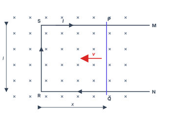
- CBSE 2023Set 55/1/11 markMCQQ.Figure shows a rectangular conductor PSRQ in which the movable arm PQ has resistance r and the resistance of PSRQ is negligible. When PQ is moved with a velocity v, the magnitude of the emf induced does not depend on :(a) magnetic field (B)(b) velocity (v)(c) resistance (r)(d) length of PQ
›Reveal solutionSolution
The induced emf in a moving conductor in a uniform magnetic field is purely a motional emf given by E=Blv, which depends only on the magnetic field B, the length l of the moving arm, and its velocity v. The resistance r of the arm does not appear in this expression — it only determines the current that flows. Hence the correct answer is (c).
The key idea here is the distinction between induced emf and induced current. Many students mix them up, especially when a problem mentions resistance. Let's clear that up first.
When a conductor moves in a magnetic field, the free electrons inside it experience a magnetic Lorentz force q(v×B). This force pushes charges along the conductor, creating a potential difference — that potential difference is the motional emf. It is a direct consequence of the motion and the field, nothing else.
The resistance of the conductor only comes into the picture when you ask: "How much current flows as a result of this emf?" That's Ohm's law: I=E/R. But the emf itself is independent of the resistance.
Now let's walk through the problem step by step.
-
Identify the source of emf. The arm PQ is the only part of the loop that is moving. The rest of the loop (PSRQ) is stationary and has negligible resistance. So the entire induced emf in the loop is generated across PQ.
-
Write the expression for motional emf. For a straight conductor of length l moving with velocity v perpendicular to a uniform magnetic field B, the motional emf is:
E=Blv
This is derived from the work done per unit charge by the magnetic force: Fm=qvB, so the electric field set up inside the conductor is E=vB, and over length l, the potential difference is El=Blv.
-
Check each option against this formula.
- (a) magnetic field B — appears in E=Blv. So emf does depend on it.
- (b) velocity v — appears directly. So emf does depend on it.
- (d) length of PQ — that's l in the formula. So emf does depend on it.
- (c) resistance r — does not appear in E=Blv. So emf does not depend on it.
-
Address the common confusion. The problem says the movable arm PQ has resistance r, while the rest of the loop has negligible resistance. The total loop resistance is therefore r. The induced current in the loop would be I=E/r=Blv/r, which does depend on r. But the question asks about the emf, not the current. The emf is generated by motion, not by resistance.
Watch outA classic mistake is to see r in the circuit and assume it affects the emf. Remember: emf is the cause, current is the effect. Resistance only limits the effect, not the cause. The motional emf is determined entirely by B, l, and v — the three factors that govern how strongly charges are pushed by the magnetic field.
TipA quick way to check: if you doubled the resistance r while keeping B, l, and v the same, would the voltmeter reading across PQ change? No — the same motional emf would appear, but less current would flow. The emf is a property of the motion, not the material.
✓Final answerThe induced emf does not depend on the resistance r of the movable arm, so the correct option is (c).
-
- CBSE 2023Set ANNUAL1 markMCQQ.Direction of current induced in a wire moving in a magnetic field is found using(1) Fleming's left hand rule(2) Fleming's right hand rule(3) Ampere's rule(4) none of these
›Reveal solutionSolution
Fleming's right-hand rule gives the direction of INDUCED current (a motional-EMF/generator situation); the left-hand rule instead gives the direction of FORCE on a current-carrying conductor (a motor situation).
Orient the thumb, forefinger and middle finger of the right hand mutually perpendicular: thumb points along the direction of motion of the conductor, forefinger along the magnetic field, and the middle finger then gives the direction of the induced current.
✓Final answer(2) Fleming's right hand rule.
- CBSE 2022Set ANNUAL1 markQ.When a metal rod of length l is placed normal to a uniform magnetic field B and moved with a velocity v perpendicular to the field, the induced emf (called motional emf) across its end is ............ .
›Reveal solutionSolution
The induced (motional) emf across the ends of the rod is ε=Bvl.
When a conducting rod of length l moves with velocity v perpendicular to a uniform magnetic field B (with B, v and the rod's length mutually perpendicular), each free charge experiences a magnetic force qvB. This separates charge until an electric field balances it, producing an emf.
The rod sweeps area at rate dtdA=lv, so by Faraday's law
ε=BdtdA=Bvl.
✓Final answerε=Bvl.
- CBSE 2020Set 55/2/11 markQ.A conducting rod of length l is kept parallel to a uniform magnetic field B. It is moved along the magnetic field with a velocity v. What is the value of emf induced in the conductor ?
›Reveal solutionSolution
When a rod moves parallel to a magnetic field, the velocity and field are aligned, so the magnetic flux through any loop remains constant and no emf is induced. The answer is zero.
Why motional emf depends on perpendicular motion
Motional emf arises when a conductor cuts through magnetic field lines. The physical picture: as the rod moves, the magnetic force F=q(v×B) pushes charge carriers along the rod, creating a potential difference. This force—and hence the emf—depends critically on the component of velocity perpendicular to the magnetic field.
The motional emf in a straight rod is given by
E=∫(v×B)⋅dl
For a uniform field and velocity, this simplifies to
E=(v×B)⋅l
where l is the length vector along the rod. The cross product v×B measures how much the velocity is perpendicular to the field. When v and B are parallel (or antiparallel), this cross product vanishes.
Step-by-step analysis
-
Identify the geometry
The rod of length l is parallel to B, and it moves with velocity v along the direction of B. So v∥B.
-
Compute the cross product
Since v and B point in the same (or exactly opposite) direction, the angle θ between them is either 0° or 180°. The magnitude of the cross product is
∣v×B∣=vBsinθ=vB⋅0=0
- Evaluate the motional emf Substituting into the emf formula,
E=(v×B)⋅l=0⋅l=0
- Physical interpretation via flux Alternatively, think of Faraday's law: E=−dtdΦB. As the rod moves parallel to B, it sweeps out an area whose normal is perpendicular to B. The flux through that area is ΦB=B⋅A=0 because B⊥A. No change in flux means no induced emf.
Watch outA common mistake is to think "motion + magnetic field = emf." The motion must have a component across the field lines. Parallel motion does not cut field lines and produces no emf.
✓Final answerThe emf induced in the conductor is 0.
-
🎓Unlock everything free for 14 days
- ✓Full step-by-step solutions
- ✓Concept-first explanations
- ✓Methods, shortcuts & mistakes
- ✓PYQ mapping + timed mock tests
Full access for 14 days. No credit card required.